
Stand Welding Rotators
Enquire Now
Get the Full Product Brochure
Discover detailed specifications, features, and configurations of our machinery. Download the brochure to explore how our solutions can meet your industry’s processing needs with efficiency and reliability.
Stand Welding Rotators
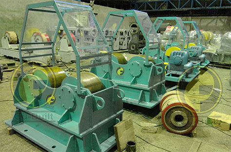
Cubuilt Engineers are a leading manufacturer of welding rotators of various types, such as Stand Welding Rotators, Conventional Type Welding Rotators, Self Centering Type Welding Rotators, Pipe Welding Rotators, Blasting and Painting Welding Rotators, Hydraulic Shell to Shell Fit Up Welding Rotators.
Stand Rotator has two units, one is Drive Unit, and the other is the Idler unit. The frame is constructed of plate fabrication precisely machined to maintain the proper level and alignment. These are mainly used as Motorized Stand for Assembly & Maintenance of LP/ HP Turbine Rotors, Generator Rotors, etc.
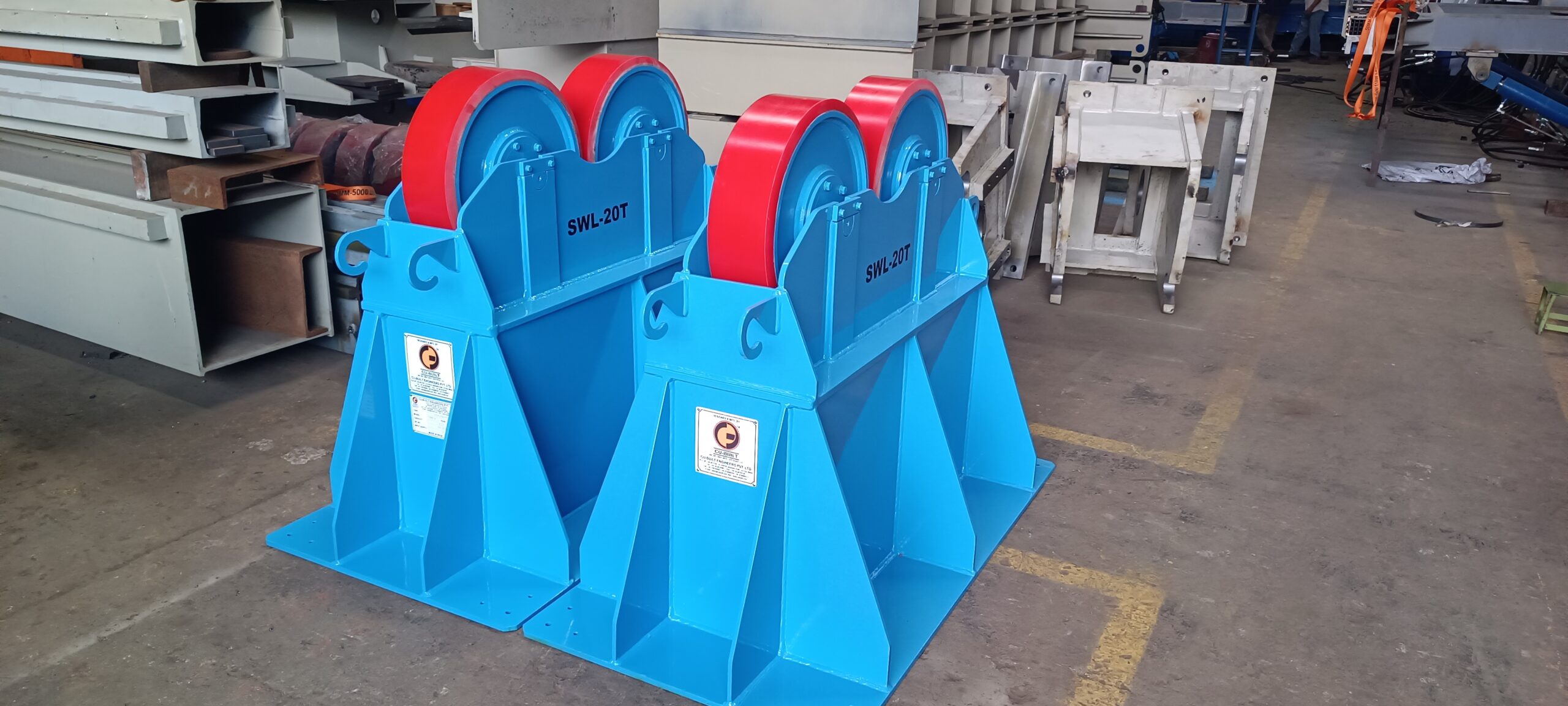
Stand Welding Rotators consist of two main units:
Drive Unit: Equipped with a motor and drive system to rotate the workpiece efficiently.
Idler Unit: Supports the opposite end of the workpiece without any drive mechanism.
The frame of the rotator is constructed from high-strength plate fabrication and is precisely machined to ensure proper level and alignment. This ensures smooth and stable rotation, even for heavy or oversized workpieces.
These rotators are primarily used as motorized stands for the assembly and maintenance of LP/HP turbine rotors, generator rotors, and other large cylindrical components. They are ideal for heavy-duty industrial applications where precision, reliability, and ease of operation are critical.
Drive Type
AC VFD
Gear Stages
2+1
Rotation
360°
Load Capacity
Custom
Product Overview
Precision-Stand Welding Rotators
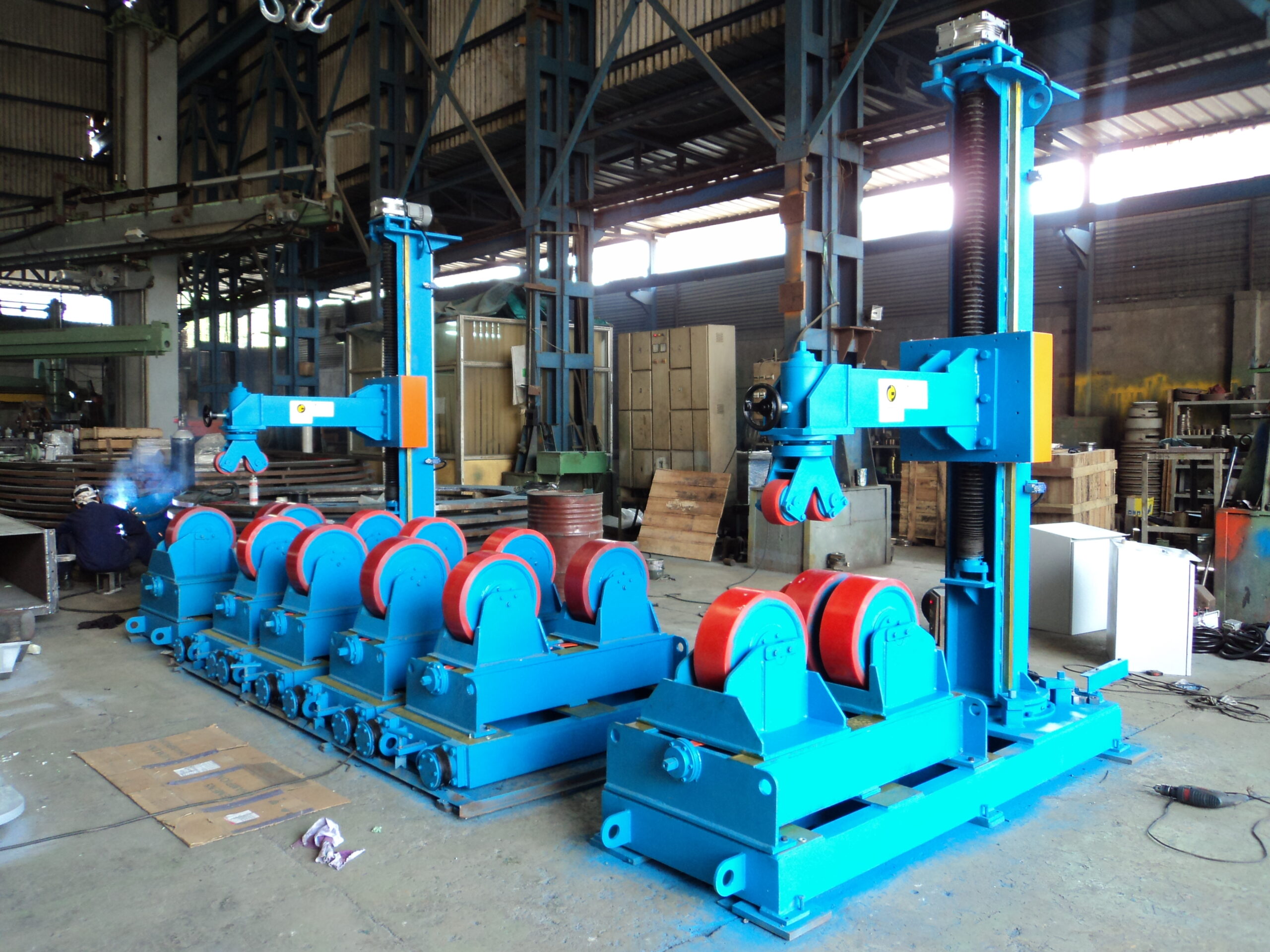
Cu-Built’s Stand Welding Rotators are heavy-duty motorised stands built for the assembly, maintenance, and inspection of LP/HP turbine rotors, generator rotors, and compressor shafts. Unlike conventional welding rotators that cradle a job on external rollers, Stand Rotators support the workpiece through its shaft journals — keeping the rotor’s centreline perfectly horizontal with minimal run-out throughout the operation.
Each system includes a motorised Drive Unit (AC VFD-driven gearbox) and a passive Idler Unit, both mounted on precision-machined plate-fabricated frames to ensure level, co-axial support. Every unit is custom-built to the client’s rotor dimensions, journal diameter, weight, and speed range — with full installation and commissioning included.
For circumferential seam welding on cylindrical shells, also see our Self Aligning Welding Rotators and Hydraulic Shell to Shell Fit Up Welding Rotators.
Key Advantages
- Precision-machined frames maintain co-axial alignment between Drive and Idler units for low run-out rotation
- Journal-support design handles turbine and generator rotors that conventional roller rotators cannot accommodate
- AC VFD drive delivers stepless, ultra-low-speed rotation — critical for rotor balancing and inspection passes
| Technical Specifications | Table Header |
|---|---|
|
Primary Application |
Assembly, maintenance and inspection of LP/HP turbine rotors, generator rotors, compressor shafts
|
|
Support Type |
Journal / shaft-stub support (not external roller cradle)
|
|
Load Capacity |
Customised to rotor weight (light to several hundred tonnes)
|
|
Drive System |
AC Motor with AC Variable Frequency Drive (VFD)
|
|
Speed Variation |
Stepless, constant torque — ultra-low to operational speeds
|
|
Rotation |
360° continuous
|
|
Gear Stages |
2+1 — double-reduction worm gearbox + spur pinion & gear
|
|
Frame Construction |
High-strength plate fabrication, precision-machined after welding
|
Engineering Excellence
Core Technology
Precision-Machined Frame Structure
The frame is plate-fabricated from high-strength structural steel, stress-relieved, then precision-machined on a CNC boring mill after welding. This post-weld machining step is what guarantees the support surfaces are level and co-axial — not just nominally flat. The result is a rotor that runs true from the first revolution, with minimal time spent on shimming or realignment at site.
AC VFD Ultra-Low Speed Drive
An AC motor paired with a Variable Frequency Drive and a 2+1 stage gear reduction delivers the very low surface speeds — sometimes fractions of an RPM — needed for rotor inspection, balancing, and slow-speed assembly tasks. The VFD also enables smooth inching (jog) operation so the operator can rotate the rotor by precise angular increments without overshoot, which is critical when indexing to specific blade or winding positions.
Drive + Idler Two-Unit Architecture
Separating the drive function into one unit and the support function into another gives the system two important advantages: the Idler Unit can be positioned independently at any distance from the Drive Unit to suit any rotor span, and the rotor weight is distributed evenly across two support points rather than cantilevered from one. This load distribution protects rotor journals and makes the assembly statically determinate — simpler to level and align on the shop floor.
Knowledge Base
What Is a Stand Welding Rotator?
A stand welding rotator — also referred to as a motorised rotor stand, turbine rotor turning stand, or journal-support rotator — is a heavy-duty motorised support system that rotates large cylindrical components such as LP/HP turbine rotors, generator rotors, compressor shafts, and large motor armatures by holding them at their shaft journals or trunnion stubs. This distinguishes them from conventional welding rotators, which support and rotate a workpiece by cradling its outer cylindrical surface on pairs of driven and idler rollers.
The distinction matters because turbine and generator rotors often have complex external profiles — blades, windings, flanges, or coupling hubs — that make it impossible to rest the rotor on external rollers. The journals are the only geometrically simple, hardened, and precisely dimensioned surfaces on the rotor that are suitable for supporting its full weight during slow rotation. Stand Rotators are built around this constraint: the support bearings or V-blocks are sized and positioned to contact the journals only, keeping the rotor’s sensitive surfaces clear of the machine.
In power generation and heavy engineering, stand rotators are used during turbine overhaul (rotating the rotor for blade inspection, replacement, or blending), generator rewind (indexing the rotor to position each winding slot), compressor assembly (fitting and torquing impellers), and quality inspection (measuring run-out across the rotor length with a dial indicator while slowly rotating). The motorised drive with AC VFD control is essential for all these tasks because the operator needs to move the rotor at a precise, controllable speed — sometimes as slow as one revolution per minute or less — and to stop and hold at exact angular positions.
Cu-Built’s stand rotators are custom-engineered to each client’s rotor specification and are widely used in power generation, heavy engineering, and defence manufacturing. For standard cylindrical shell welding applications, explore the full welding rotator range or the welding column and boom systems for complete circumferential welding cells.
Related Product
Questions Asked For Stand Welding Rotators
Do you provide both supply and installation?
Yes, we provide complete supply, installation, testing, and commissioning services.
Are these systems suitable for industrial facilities?
Yes, we provide complete supply, installation, testing, and commissioning services.
Can fire fighting systems be customized for small spaces like homes and offices?
Yes, we provide complete supply, installation, testing, and commissioning services.
Do you provide maintenance after installation?
Yes, we provide complete supply, installation, testing, and commissioning services.