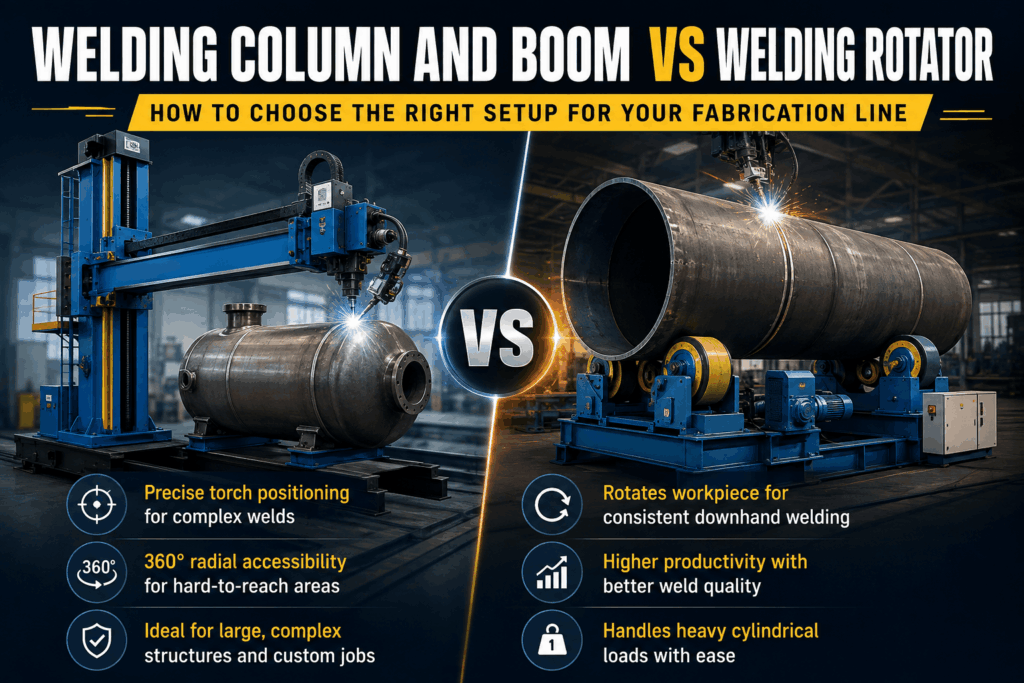
Welding Column and Boom vs Welding Rotator: How to Choose the Right Setup for Your Fabrication Line
Modern heavy industrial fabrication demands extreme precision, high deposition rates, and absolute mechanical consistency. When managing a workshop that fabricates pressure vessels, storage tanks, large-diameter pipelines, or wind turbine towers, relying solely on manual welding techniques creates significant operational bottlenecks. Manual positional welding often leads to inconsistent bead profiles, increased worker fatigue, longer cycle times, and higher repair costs. Transitioning to automated arc welding requires careful selection of the right material handling and torch manipulator equipment.
The two primary systems driving modern industrial shop floors are column and boom manipulators and turning roll assemblies. Understanding Welding Column and Boom vs Welding Rotator: How to Choose the Right Setup for Your Fabrication Line is essential before making a capital equipment investment. Choosing the correct setup—or integrating both into a unified welding cell—directly determines your workshop’s throughput capacity, structural safety, and return on investment (ROI).
What is a Welding Column and Boom Manipulator?
A Welding Column and Boom system (often referred to in heavy industry as a welding head manipulator) is designed to position and traverse an automated welding torch over complex or large workpieces with sub-millimeter precision.
Core Architecture and Structural Mechanics
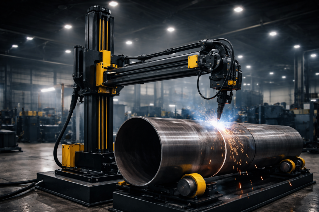
The machine features a heavy-duty vertical column anchored either to a stationary baseplate or mounted onto a motorized travel carriage that runs on shop floor rails. A horizontal arm—the boom—moves up and down along the column and extends or retracts horizontally.
- Light and Extra-Light Duty Models: Vertical movement is typically managed through a precision lead screw mechanism, providing smooth travel for heights and reaches up to 3 meters by 3 meters.
- Medium and Heavy-Duty Models: Engineered with a rack-and-pinion drive paired with a counterweight system housed inside the column. High-tensile metallic wire ropes support the counterweight assembly, ensuring smooth vertical lift without overburdening the drive motor.
- Integrated Safety Provisions: Industrial-grade systems feature anti-fall safety mechanisms to lock the boom in place in the event of power loss or mechanical failure, protecting both personnel and workpieces.
By delivering 360-degree radial torch accessibility, a column and boom manipulator allows an operator to execute long longitudinal seam welds or internal seam welds inside deep vessels without requiring manual torch re-positioning.
What is a Welding Rotator (Turning Rolls)?
While a column and boom controls the movement of the welding torch, a welding rotator controls the movement of the workpiece.
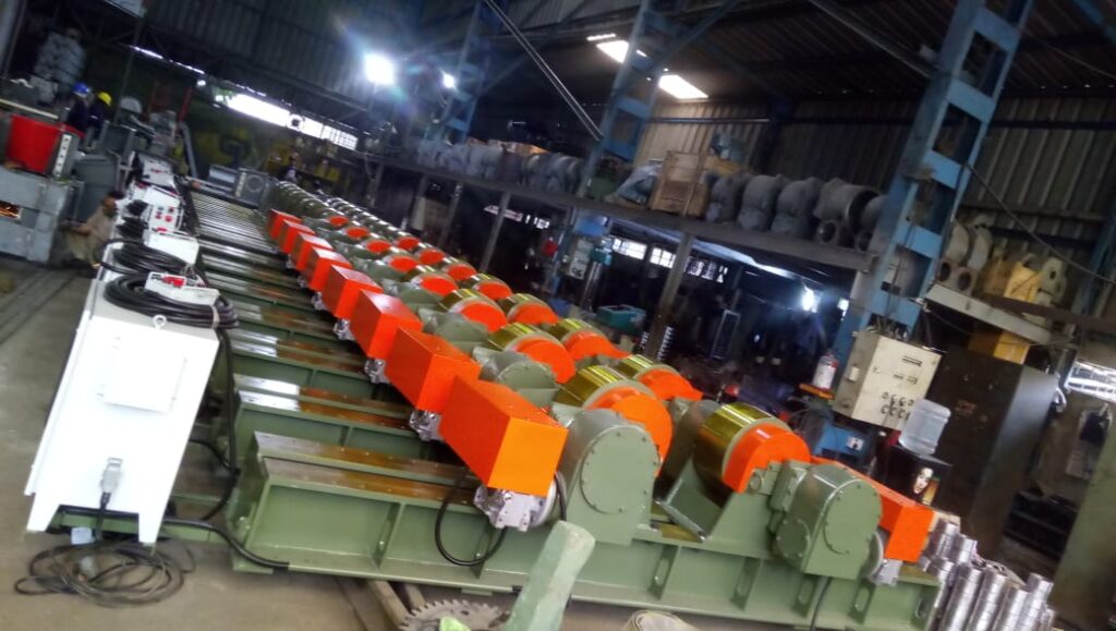
A welding rotator system consists of a powered drive unit and one or more passive idler units. The drive unit utilizes an electric motor and gearbox to turn heavy-duty rollers, which rotate cylindrical or conical steel shells at a controlled, pre-set surface speed.
Operating Principles and Key Mechanisms
By rotating the workpiece under a stationary arc, turning rolls keep the weld pool in the flat, downhand (1G/1F) position. Downhand welding utilizes gravity to improve puddle control, allowing for higher welding currents, larger wire diameters, deeper penetration, and faster travel speeds.
- Polyurethane (PU) Rollers: Polyurethane or grooved PU wheels provide high traction while preventing surface contamination or mechanical damage on stainless steel and alloy shells.
- Steel Wheels: Used for extremely heavy, thick-walled carbon steel vessels where point loads exceed rubber load capacities.
- AC VFD Drive Platforms: Variable Frequency Drives deliver smooth, step-less rotation speed control at constant torque across the full speed range, eliminating jerky motion during seam deposition.
Specialized configurations like pipe rotators cater to small-bore piping, while larger turning rolls support massive pressure vessels weighing over 1,000 tons.
Detailed Comparison: Column and Boom vs Welding Rotator
Evaluating Welding Column and Boom vs Welding Rotator: How to Choose the Right Setup for Your Fabrication Line requires analyzing how each machine manipulates the welding interface. The key difference lies in motion control: one moves the welding head across a stationary or moving workpiece, while the other rotates a cylindrical job beneath a stationary welding head.
| Feature / Metric | Welding Column and Boom | Welding Rotator (Turning Rolls) |
| Primary Motion | Moves the welding head vertically, horizontally, or along rail tracks. | Rotates cylindrical workpieces around a central axis. |
| Ideal Workpiece Geometries | Flat plates, longitudinal seams, box girders, internal/external vessel seams. | Cylindrical, conical, spherical, or pipe assemblies. |
| Weld Seam Orientation | Longitudinal (straight-line) welds, high-reach joints, deep internal seams. | Circumferential (360-degree round) seams. |
| Weld Process Compatibility | SAW, Heavy MIG/MAG, TIG, Plasma Arc Welding (PAW). | SAW, MIG/MAG, FCAW, TIG. |
| Floor Space Footprint | Vertical clearance-heavy; can be mounted on rail tracks. | Horizontal clearance-heavy; low-profile floor installation. |
| Crane Dependency | Low (once setup is secured). | Moderate to High (requires cranes for loading/unloading shells). |
| Primary Automation Benefit | Replaces manual welder reach; delivers consistent linear travel speed. | Maintains flat downhand welding; eliminates manual shell turning. |
Key Types of Welding Rotators Used in Industrial Fabrication
Selecting the right turning roll setup depends on your shop’s workpiece variation, production volume, and wall-thickness requirements.
1. Conventional Type Welding Rotators
Conventional rotators feature roller housings that are manually adjusted along a structural bed frame using bolt slots or lead screw mechanisms to accommodate varying shell diameters.
- Best For: High-capacity production lines handling standardized workpiece diameters over long runs.
- Key Advantage: High structural rigidity and weight capacity, supporting heavy vessels up to and exceeding 1,000 tons.
2. Self-Aligning Welding Rotators
Self-aligning turning rolls utilize pivoting wheel bracket assemblies that automatically adjust their angle when a shell is lowered onto the bed.
- Best For: Job shops frequently changing vessel diameters throughout the workday.
- Key Advantage: Eliminates manual adjustment downtime. By distributing weight across four contact points per unit, it helps reduce localized deformation on thin-walled tanks.
3. Self-Centering Welding Rotators
These units use a synchronized lead screw mechanism to move both roller assemblies toward or away from the center line simultaneously.
- Best For: Fabrication lines requiring a fixed centerline regardless of workpiece outer diameter.
- Key Advantage: Keeps the top center of the pipe at a consistent height, reducing the need to re-adjust torch height when changing pipe sizes.
4. Specialized Rotator Configurations
- Fit-Up Rotators: Equipped with hydraulic alignment cylinders to bring shell sections together for tack welding.
- Blasting and Painting Rotators: Built with sealed bearing housings, blast-monitoring panels, and protective wheel covers to withstand grit blasting and spray paint environments.
Key Types of Welding Column and Boom Manipulators
Selecting the right column and boom depends on the height, length, and weight of your target fabrications.
Light to Extra-Light Duty Manipulators
- Designed for working envelopes up to 3 meters vertical reach by 3 meters horizontal stroke.
- Utilize lead-screw vertical elevation mechanisms, making them ideal for light-gauge pipe shops, small vessel fabricators, and compact automation cells.
Medium and Heavy-Duty Manipulators
- Built for severe industrial service, reaching heights and strokes from 4×4 meters up to 10×10 meters or larger.
- Feature precision rack-and-pinion boom drives, counterweight safety systems, anti-fall mechanisms, and stiff box-section columns.
- Can be configured as a fixed base, manual trolley base, or motorized track-traveling base.
Technical Selection Framework: 6 Factors for Your Setup
When deciding between a column and boom, a turning roll system, or a combined integration, evaluate these six technical factors on your shop floor:
- Workpiece Geometry and Shell Structural Stability: Structural box girders or flat panels require a column and boom manipulator. Round tanks or boiler drums require turning rolls to provide rotation for continuous downhand welding.
- Seam Type (Longitudinal vs. Circumferential Welding): Longitudinal straight-line seams require the linear travel of a column and boom. Circumferential girth welds around a cylinder require turning rolls to rotate the shell beneath a stationary torch.
- Welding Process and Equipment Weight: Heavy Submerged Arc Welding (SAW) systems—including wire pay-off drums, flux recovery hoppers, and multi-wire heads—add significant weight to the torch assembly. A heavy-duty column and boom provides the structural rigidity needed to carry this payload without deflection.
- Vessel Diameter and Wall Thickness Dynamics: Thin-walled stainless steel shells are prone to oval distortion under high point loads. Self-aligning rotators distribute weight across four wide polyurethane-coated wheels to preserve roundness.
- Shop Floor Layout and Crane Availability: Turning rolls keep heavy vessels lower to the floor during girth welding, reducing overhead crane usage. Mounting a column and boom on a motorized travel carriage allows a single operator to serve multiple welding stations along a track.
- Weld Quality and Non-Destructive Testing (NDT) Compliance: High-pressure piping and nuclear-grade vessels undergo strict Radiographic and Ultrasonic testing. Automated systems maintain precise travel speeds and arc length parameters, helping ensure first-time pass rates during NDT evaluations.
For official safety guidelines and engineering standards covering automated arc welding machinery and shop floor safety practices, consult the guidelines established by the American Welding Society (AWS) and the international directives outlined by the International Organization for Standardization (ISO).
Why the Ultimate Solution is Often a Combined Automated Welding Cell
For high-volume tank manufacturers, pressure vessel shops, and wind tower fabricators, choosing between a column and boom or a turning roll system is not always an either/or decision. The most efficient fabrication lines integrate both into a synchronized welding cell.
Benefits of Synchronized System Integration
- Complete Seam Coverage: The column and boom moves along the vessel to weld longitudinal seams. Once complete, the operator engages the rotator to turn the vessel while the column and boom holds the torch stationary over circumferential girth seams.
- Unified Control PLC Interface: Advanced automated welding cells link the VFD motor controls of the rotator directly to the boom’s horizontal drive and welding power source. This allows the operator to adjust rotation speeds, torch tracking, and wire feed parameters from a single pendant or touchscreen interface.
- Reduced Material Handling: Rather than transferring heavy vessels between different stations for longitudinal and circumferential welds, the entire welding cycle takes place within a single integrated automation zone.
Real-World ROI: Calculating the Impact of Automation
Upgrading from manual arc welding to an automated setup delivers measurable productivity and financial improvements:
- Higher Deposition Rates: Submerged Arc Welding (SAW) on a heavy-duty column and boom and rotator cell yields deposition rates of 8 to 15+ kg/hour, compared to 1.5 to 2.5 kg/hour with manual SMAW/MIG welding.
- Higher Duty Cycles: Manual welding typically operates at a 30% to 40% duty cycle due to operator fatigue and positioning downtime. Automated cells achieve up to an 80% to 90% arc-on duty cycle.
- Reduced Consumable Waste: Precise VFD speed control reduces weld over-fill, saving thousands of dollars annually in filler wire and shielding gas/flux usage.
- Lower Repair Rates: Eliminating start-stop defects reduces grinding, gouging, and re-welding labor expenses.
Transforming Shop Floor Output with Industrial Automation
Optimizing heavy fabrication throughput requires selecting equipment built specifically for demanding production environments. Off-the-shelf positioners often lack the structural rigidity, fine speed control, and built-in safety features needed for continuous heavy-duty welding.
At Cu-Built Engineers, we engineer customized industrial automation solutions designed to eliminate material handling bottlenecks and elevate weld quality. Our heavy-duty column and boom manipulators, conventional turning rolls, self-aligning rotators, and specialized pipe rotators are engineered to perform reliably under demanding manufacturing conditions.
Whether you need a standalone pipe rotator or a fully integrated Submerged Arc Welding cell, our engineering team provides end-to-end support—from initial design consultation and system configuration to installation and ongoing technical service.
Ready to upgrade your fabrication line performance?
Contact the Cu-Built Engineering Team Today to request a technical consultation, download detailed product specifications, or receive a customized quote tailored to your facility’s production goals!
Frequently Asked Questions (Q&A)
Q1: What is the main structural difference in vertical elevation between light-duty and heavy-duty Column and Boom systems?
Light and extra-light duty column and boom systems (typically up to 3m x 3m working envelope) utilize a precision lead-screw mechanism for vertical movement. Medium and heavy-duty models use a heavy-duty rack-and-pinion drive system combined with an internal counterweight arrangement and high-tensile wire ropes to ensure smooth, safe, and positive elevation under heavy payload conditions.
Q2: How do I prevent thin-walled stainless steel tanks from deforming on welding rotators?
Thin-walled vessels should be mounted on a Self-Aligning Welding Rotator equipped with Polyurethane (PU) coated rollers. Self-aligning mechanisms automatically adjust their wheel brackets to distribute the shell’s weight across four contact points per unit (eight contact points across a drive/idler pair). This minimizes point loading and helps prevent localized shell deformation.
Q3: Can a Column and Boom handle both Submerged Arc Welding (SAW) and MIG/TIG welding processes?
Yes. Column and boom manipulators serve as versatile universal torch delivery platforms. They can be fitted with heavy single or multi-wire SAW heads, flux recovery units, MIG/MAG torches, FCAW configurations, or TIG welding systems depending on your material process requirements.
Q4: Which system is better for welding straight longitudinal seams on flat plates or rolled shells?
A Column and Boom manipulator is required for welding straight longitudinal seams. The boom extends horizontally along the straight seam at a controlled, constant travel speed while the workpiece remains clamped or stationary. Turning rolls only rotate objects and cannot travel linearly down a seam.
Q5: Why is Variable Frequency Drive (VFD) speed control critical for welding turning rolls?
A VFD provides step-less speed adjustment while maintaining constant motor output torque across the entire rotation range. Precise, jitter-free surface speed rotation is essential to maintain a stable weld pool, prevent heat-input fluctuations, and ensure uniform bead appearance during continuous circumferential welding.