cubuilt

Author name: webadmin

wind tower manufacturing
Blog

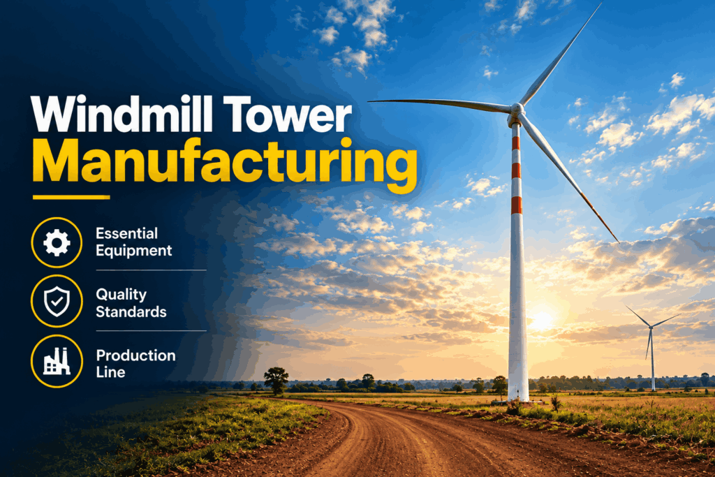
How Wind Tower Manufacturing Equipment Is Powering India’s Renewable Energy Push

India’s energy landscape is undergoing a massive paradigm shift. As the nation races to meet its aggressive climate commitments, clean energy is moving from the margins directly into the mainstream. At the absolute heart of this green transition stands the wind energy sector, an industry tasking engineers and fabricators with building unprecedented structural capacities. While the soaring, elegant sweeps of wind turbine blades capture the public’s imagination, the true marvel of engineering lies beneath them: the colossal, heavy steel towers that hold these behemoths steady against unforgiving elements. The production of these giant support structures requires specialized engineering systems. High-precision wind tower manufacturing equipment is driving India’s renewable energy push by transforming massive steel plates into structurally sound, highly reliable utility assets. Without these automated, high-capacity machinery setups, scaling up the nation’s clean power grid would be virtually impossible. The Scale of India’s Green Ambitions and the Need for Robust Wind Energy Infrastructure India has established a global benchmark by targeting a massive expansion of its green power grid, aiming for a significant share of non-fossil fuel capacity over the coming decades. Achieving these targets requires a dramatic acceleration in both terrestrial and marine installations. Consequently, the reliance on high-capacity wind energy infrastructure has never been more pronounced. To harvest stronger, more consistent winds, modern turbines are scaling to towering heights. The structural stress applied to these systems is immense, requiring support structures that can bear hundreds of tons of dynamic weight. Building towers that can reliably withstand these forces requires heavy-duty engineering solutions. Specialized machinery plays a crucial role in shaping, aligning, and securing these mega-structures to guarantee structural integrity over decades of operation. Technical Breakdown: How Wind Tower Manufacturing Equipment Automates Clean Energy Production Constructing a modern wind turbine tower is a complex multi-stage process that requires deep expertise in heavy metal fabrication. Standard manufacturing tools fall short when dealing with dimensions of this scale. Specialized heavy industrial automation is required to manage the unique geometries and strict tolerances demanded by the global green energy market. Heavy Duty Plate Rolling and Forming The fabrication process starts with massive structural steel sheets. A high-capacity plate rolling machine is utilized to bend these flat, heavy-gauge steel pieces into precise conical or cylindrical shells. Given that a single tower consists of multiple segments with varying diameters and wall thicknesses, these rolling systems must maintain absolute precision to ensure perfect alignment during subsequent production phases. Advanced Fitting and Structural Alignment Once individual steel plates are rolled into cylinders, they must be aligned and welded together. Specialized heavy-duty shell-to-shell fit-up rotators play a crucial role here. These automated systems support, rotate, and precisely position the heavy steel sections, minimizing manual adjustments and accelerating structural assembly. Precision Flange Integration Integrating internal and structural connections is a critical step in ensuring the overall stability of the structure. Tower flange welding demands precision, as the massive forged flanges at the ends of each tower section must be perfectly square and true. Any minor deviation could cause misalignment during final field assembly, putting the structural integrity of the entire turbine assembly at risk. Onshore vs. Offshore Wind Tower Fabrication: Meeting Varied Structural Challenges As India expands its renewable installations, engineers must design equipment tailored for distinct geographic and environmental conditions. Engineering Factor Onshore Wind Tower Equipment Offshore Wind Tower Fabrication Material Thickness Medium to high-gauge structural steel Extreme heavy-gauge, corrosion-resistant steel Diameter Dimensions Constrained by overland transit limits Significantly larger diameters for maritime stability Welding Requirements Standard high-yield structural welding Multi-pass, fatigue-resistant automated welding Surface Treatment Standard weatherproofing coatings Multi-layer marine coatings to resist salt spray Deploying dedicated onshore wind tower equipment allows manufacturers to optimize workflows for land-based projects, where logistics and transport routes often cap the maximum diameter of individual tower segments. Conversely, offshore wind tower fabrication presents unique engineering challenges. Marine installations face harsher environments, including continuous salt spray, wave impacts, and high wind forces. To withstand these conditions, offshore structures require thicker steel walls, larger diameters, and enhanced metallurgical integrity, requiring specialized heavy-duty fabrication equipment. Key Machinery Driving the Wind Turbine Tower Manufacturing Sector Scaling up production to meet commercial demand requires transitioning from manual workflows to fully automated systems. Modern manufacturing facilities utilize integrated production lines designed to handle heavy components efficiently. 1. Automated Columns & Booms (Welding Manipulators) Automated column and boom systems position welding heads with high precision along both internal and external seams. By automating the Submerged Arc Welding (SAW) process, these systems deliver deep-penetration, defect-free welds that meet strict non-destructive testing (NDT) criteria. 2. Specialized Welding Rotators Heavy-duty fit-up and turning rotators handle the rotation of massive steel cylinders during assembly. These systems maintain synchronized rotation speeds to ensure uniform heat distribution and consistent weld profiles across the entire circumference of the workpiece. 3. Integrated Internal Component Assembly Stations Beyond the outer steel shell, a functional tower requires an array of internal systems. Dedicated tower internals assembly stations allow for the systematic installation of platforms, ladders, high-voltage cabling, and lift mechanisms, ensuring these internal components are securely anchored before the tower leaves the factory floor. Overcoming Heavy Fabrication Bottlenecks in the Wind Sector The manufacturing of utility-scale power infrastructure presents distinct production and logistical challenges. Handling massive, heavy-gauge components requires careful process control to avoid structural deformities and maintain manufacturing throughput. Managing geometric tolerances across large components is a frequent challenge during tower section fabrication. Even minor deviations during rolling or welding can distort a cylinder’s roundness, leading to fit-up issues during final assembly. Advanced heavy fabrication systems resolve this by utilizing real-time monitoring and adaptive controls to adjust tracking and pressure during production. Additionally, managing the sheer weight of these sub-assemblies requires reliable material handling systems. Heavy industrial cranes, goliath gantries, and specialized transport systems are essential for moving completed sections safely between welding, blasting, painting, and storage yards. Why India-Based Manufacturing is Crucial for Global Renewable Energy Goals Establishing robust local supply chains is key to making clean energy projects economically viable. Relying heavily on

welding rotator
Uncategorized

Welding Rotator: Types, Applications, and Benefits for Industrial Manufacturing

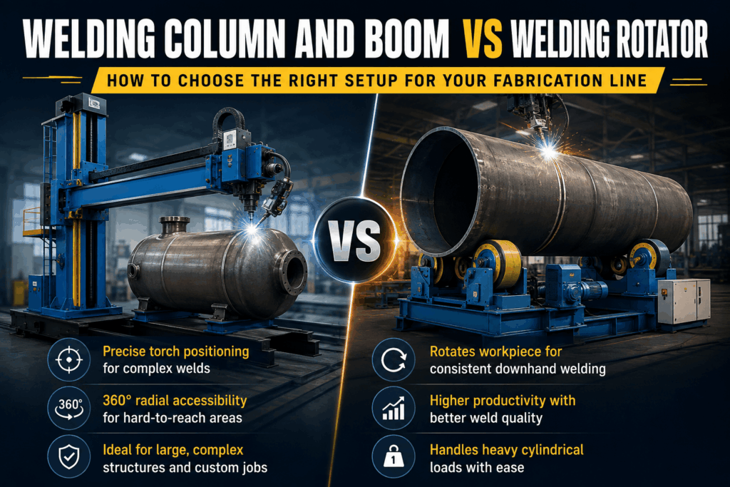
The demands of modern industrial manufacturing require precision, speed, and uncompromising safety. When dealing with massive cylindrical workpieces—such as pressure vessels, storage tanks, pipelines, and heavy structural columns—manual manipulation is not only inefficient but highly hazardous. This is where the welding rotator becomes an indispensable asset on the factory floor. A welding rotator is a specialized piece of heavy-duty engineering equipment designed to rotate cylindrical or conical objects during welding and fabrication processes. By maintaining a constant, controlled speed, these machines allow welding torches (whether manual, semi-automatic, or fully automatic) to remain stationary while the workpiece rotates uniformly. This configuration ensures smooth, deep-penetration welds that meet rigorous quality standards. Integrating an industrial welding rotator into your production line eliminates the need for cranes, forklifts, and complex rigging systems to turn heavy loads. As structural fabricators face tightening deadlines and stricter compliance standards, choosing the right welding rotator machine is the ultimate key to maximizing throughput, eliminating operational bottlenecks, and protecting skilled technicians. What is a Welding Rotator? At its core, a welding rotator—often referred to globally as welding turning rolls—consists of a motorized drive unit and one or more idler units. The drive unit houses an electric motor and gearbox that powers heavy-duty wheels (usually coated in polyurethane, rubber, or made entirely of steel) to turn the workpiece. The idler units provide additional structural support along the length of the vessel or pipe. By providing a stable, motorized rotating platform, this fabrication welding equipment ensures that circumferential seams are welded continuously in the ideal flat downhand position (1G/PA). Welding in the flat position yields superior metallurgical properties, better bead aesthetics, and a significantly lower risk of defects like slag inclusions, porosity, or lack of fusion. Types of Welding Rotators Used in Manufacturing Different fabrication projects involve varying diameters, weights, and wall thicknesses. To accommodate these diverse manufacturing demands, a premium welding rotator manufacturer offers several distinct configurations: 1. Conventional Type Welding Rotator The conventional type welding rotator is engineered with fixed wheel centers that must be manually adjusted to accommodate different workpiece diameters. The operator moves the roller housings along the base frame using bolt slots or lead screw mechanisms. 2. Self Aligning Welding Rotator A self aligning welding rotator features independent wheel assemblies that automatically pivot and adjust their orientation to match the exact diameter of the workpiece as it is lowered onto the bed. 3. Self Centering Welding Rotator The self centering welding rotator utilizes a synchronized lead screw or mechanical linkage system to move both roller beds simultaneously toward or away from the center line. This ensures that the exact center axis of the cylindrical workpiece remains constant, regardless of its diameter. This feature is highly advantageous when integrating the rollers with fixed welding columns and booms. 4. Pipe Welding Rotator Tailored specifically for smaller diameters and rapid cycle times, a pipe welding rotator is optimized for cross-country pipeline construction, refinery piping systems, and mechanical workshop plumbing. These systems typically utilize high-traction polyurethane rollers to prevent scratching or damaging polished surfaces on exotic materials like stainless steel or duplex alloys. 5. Hydraulic Shell to Shell Fit Up Welding Rotator When aligning two separate cylindrical shells for tack welding, a standard roller is not enough. A hydraulic shell to shell fit up welding rotator incorporates hydraulic cylinders capable of shifting the rollers vertically, horizontally, and independently. This allows operators to perfectly align the joint faces, correct eccentricities, and eliminate “hi-lo” structural mismatches prior to running the main weld passes. Technical Comparison of Core Turning Roll Configurations Feature Conventional Type Rotator Self Aligning Rotator Self Centering Rotator Diameter Adjustment Manual (Bolts/Lead Screw) Automatic (Pivoting Rockers) Synchronized Mechanical Ideal Load Range Up to 1000+ Tons Up to 500 Tons Up to 200 Tons Setup Time Moderate Zero Low Thin-Wall Support Standard Excellent (4-point contact) Good Automation Compatibility Good Excellent Superior (Fixed Centerline) Key Benefits of Implementing an Automatic Welding Rotator Investing in an automatic welding rotator yields substantial financial and operational returns. If your facility is trying to decide how does a welding rotator improve welding efficiency, consider these critical advantages: 1. Unmatched Weld Quality and Defect Reduction When operators attempt to weld large cylindrical seams manually without a rotator, they must constantly stop to reposition the workpiece. Every stop-and-start introduces a high vulnerability point for defects like lack of penetration or porosity. A motorized roller ensures continuous, uninterrupted rotation, enabling consistent arc voltage and travel speed. 2. Exponential Productivity Gains By eliminating the reliance on overhead factory cranes to turn vessels step-by-step, non-productive handling time is reduced by up to 70%. Welders can keep their torches lit for longer durations, greatly increasing arc-on time and overall deposition rates. 3. Enhanced Workplace Safety Suspended heavy loads are one of the most prominent safety hazards in structural fabrication shops. Utilizing a low-profile, floor-mounted heavy duty welding rotator keeps massive steel vessels securely cradled at ground level, minimizing crane lifts and mitigating the risk of catastrophic catastrophic workplace accidents. 4. Reduced Fatigue for Professional Welders Working over overhead zones or maintaining awkward bodily positions for hours causes rapid welder fatigue, which degrades weld quality over a shift. Rotators place the weld joint directly in front of the worker at an ergonomic height, allowing them to focus strictly on puddle control. Industrial Applications Across Sectors From minor industrial piping networks to massive aerospace assemblies, high-capacity turning rolls are utilized across a vast spectrum of critical industrial landscapes: Selecting the Best Welding Rotator for Heavy Fabrication Industries Choosing the correct equipment requires evaluating more than just the gross weight of your heaviest workpiece. To source the best welding rotator for heavy fabrication industries, your engineering team must analyze the following parameters: Elevate Your Production with CuBuilt’s Engineering Solutions At CuBuilt Engineers, we specialize in designing and manufacturing top-tier industrial automation systems that tackle your toughest fabrication challenges. As a globally recognized welding rotator manufacturer, our equipment is built to withstand rugged foundry and shop floor conditions while delivering pinpoint accuracy. Whether your facility

windmill tower manufacturer
Blog

How to Choose the Right Windmill Tower Manufacturer for Your Renewable Energy Project

The global transition toward clean, sustainable energy has accelerated dramatically over the recent decade. Across the globe, wind power installations are reaching historic highs, with massive scale milestones projected to triple capacity by the turn of the decade. At the heart of every successful utility-scale project stands a foundational structural component: the wind turbine tower. This structure typically accounts for a significant portion of the entire system’s total cost. Consequently, picking a qualified Windmill Tower Manufacturer is not merely a purchasing choice. It is a critical risk mitigation step that dictates your long-term return on investment (ROI). When launching a renewable energy project, engineering teams often obsess over generator ratings, blade aerodynamics, and geographic wind speeds. While those factors dictate energy generation potential, they become irrelevant if the underlying physical support fails. A wind tower must withstand immense dynamic forces, environmental weathering, and continuous rotor vibrations over a standard operational lifespan exceeding twenty years. Therefore, you need a manufacturing partner capable of converting complex engineering blueprints into precise, heavy-duty structural steel. This comprehensive guide outlines the vital factors, technical requirements, and strategic selection steps required to pick the ideal production partner. Understanding the Structural Role of Windmill Towers Before assessing suppliers, you must understand why a tower requires specialized manufacturing processes rather than generic heavy steel fabrication. The main purpose of a wind tower goes far beyond elevating the nacelle and rotor assembly. Managing Dynamic Aerodynamic Forces A tower functions as a cantilevered beam anchored to a massive reinforced concrete foundation. It experiences multi-directional forces including: Preventing Structural Buckling and Local Collapse The primary structural threat to tubular steel towers is local collapse or geometric buckling failure caused by extreme wind loads combined with heavy vertical weight loads. To counter these hazards, modern industrial designs utilize tapered sections with varying plate thicknesses. The walls at the base are significantly thicker to withstand extreme bending forces, whereas the sections taper toward the top to minimize unnecessary top-heavy weight. Every single section transition, flange interface, and structural weld must match exact metallurgical tolerances. If any part of the fabrication process deviates from structural calculations, the tower risks experiencing catastrophic structural failure under extreme environmental conditions. Essential Evaluation Criteria for a Windmill Tower Manufacturer Choosing a reliable Windmill Tower Manufacturer requires a structured review process. You cannot evaluate suppliers based solely on initial cost estimates. Instead, you must assess their manufacturing infrastructure, quality assurance policies, and supply chain capabilities. 1. Production Capacity and Machine Infrastructure The physical dimensions of modern wind towers require specialized manufacturing facilities. Heavy industrial engineering teams should inspect the candidate’s facilities for the following structural tooling assets: 2. Quality Control Standards and Certifications Structural steel components deployed in utility-scale sustainable energy plants must comply with strict international guidelines. Verify that the company holds the following credentials: In addition, ask about their Non-Destructive Testing (NDT) capabilities. A reliable Windmill Tower Manufacturer should perform comprehensive NDT testing—such as Ultrasonic Testing (UT), Magnetic Particle Inspection (MPI), and Radiographic Testing (RT)—on 100% of critical structural welds to identify internal defects before shipping. 3. Sourcing Certified Materials The integrity of a heavy-duty tower depends entirely on the raw materials used to build it. Industrial tower manufacturing consumes high-tensile structural carbon steel plates that comply with strict global standards. Your supplier must provide full material traceability, including Mill Test Certificates (MTCs), for every steel plate received. This documentation verifies critical material properties, such as yield strength and impact toughness, which prove the steel can handle freezing temperatures and high-impact wind forces without fracturing. For detailed specifications on standard structural steel baselines, engineers can reference ASTM International to compare raw material thresholds. Technical Insights into the Manufacturing Process Understanding the core steps of the tower manufacturing process helps project managers spot potential defects and evaluate realistic production schedules. Plate Cutting and Edge Preparation The fabrication process starts with flat rectangular steel plates. Technicians use high-precision CNC oxy-fuel or plasma cutting tables to cut these plates to exact dimensions. After cutting, the edges undergo mechanical beveling to create precise V-shaped or X-shaped grooves. This shape allows automated welding machines to achieve deep weld penetration along the seams. Ferrule Rolling and Longitudinal Welding The prepared steel plates are fed into heavy hydraulic plate rollers, which bend the flat metal into perfectly round cylinders known as ferrules. Once a ferrule is rolled into shape, automated welding machines seal the open longitudinal joint. Assembling Sections and Welding Flanges To build a complete tower section, multiple ferrules are placed end-to-end on alignment rollers and welded together using circular welds. High-strength forged steel flanges are then welded to the far ends of the section. These flanges feature precision-drilled bolt holes that allow crews to bolt different sections together during on-site field assembly. Surface Treatment and Corrosion Protection Wind energy assets face severe weather conditions, ranging from hot, humid plains to freezing, corrosive offshore coastal locations. Long-term durability requires excellent surface treatment, including: Supply Chain, Shipping, and Site Logistics Because tower sections are so large, logistics and shipping costs can quickly derail a project’s budget if not managed carefully. Navigating Transportation Clearances Moving oversized cargo requires careful route planning. Tower sections frequently exceed fifteen feet in diameter and one hundred feet in length. You need to ensure the manufacturer’s facility offers easy access to major shipping corridors, rail networks, or deep-water ports. The carrier must secure special oversized transport permits and map out routes to clear low bridges, tight highway turns, and overhead utility lines. Packaging and Delivery Schedules During transit, open tower ends must be sealed with heavy-duty weather-resistant tarpaulins or rigid plastic covers. This packaging protects pre-installed internal components—such as internal platforms, access ladders, lighting systems, and power cables—from moisture, road grime, and salt spray. Furthermore, your manufacturer must coordinate production schedules with your field construction crews. Delivering tower sections too early forces you to pay for expensive storage space on-site, while late deliveries can leave expensive installation cranes sitting idle. Aligning Your Engineering Requirements with Manufacturer Technical Capabilities To

Self-aligning vs conventional welding rotators
Uncategorized

Self-Aligning vs Conventional Welding Rotators: Which to Choose?

In the heavy fabrication industry, maximizing productivity while maintaining flawless weld quality is a continuous challenge. Whether you are fabricating massive pressure vessels, wind tower sections, or small-bore process pipes, the way you support and turn your workpieces fundamentally dictates your operational throughput. This brings engineering managers and procurement heads to a critical fork in the road: self-aligning vs conventional welding rotators—which setup is truly optimal for your production floor? Investing in automated turning rolls is not merely about spinning a steel cylinder; it is an economic and structural decision. Selecting the wrong equipment configuration leads to excessive setup delays, uneven weld profiles, or structural deformation of expensive workpieces. Conversely, choosing the ideal system dramatically cuts cycle times, limits operator fatigue, and delivers a rapid return on investment. This comprehensive guide breaks down the structural differences, operational mechanics, financial implications, and application suitability of both systems. Read on to determine which machine configuration will elevate your shop floor efficiency to the next level. What Are Welding Rotators and Why Are They Essential? Before diving into the detailed comparison of self-aligning vs conventional welding rotators, it is crucial to understand the foundational role these industrial systems play. Industrial welding rotators, often called turning rolls, are specialized mechanical assemblies designed to rotate cylindrical workpieces. By spinning the job at a stable, controlled velocity, these systems allow the welding torch to remain completely stationary. This presentation consistently places the joint in the ideal downhand (flat) position. When you eliminate the need to constantly reposition a workpiece manually using overhead workshop cranes, your fabrication workflow becomes remarkably streamlined. Automated rotation minimizes crane dependency, dramatically decreases idle time between passes, and ensures deep, uniform weld penetration. This process remains vital for critical applications across sectors like oil and gas, green energy, and petrochemical processing. A standard industrial turning roll package operates using a dual-component architecture: Understanding Conventional Welding Rotators To understand the core differences between a self-aligning vs conventional welding rotators framework, we must first analyze the engineering behind the conventional design. A conventional welding rotator consists of fixed roller brackets bolted securely onto a rigid, machined base frame. Mechanical Design and Adjustment Process In a conventional setup, the roller brackets do not adapt on their own. When a new job arrives with a different outer diameter, operators must manually unbolt the roller brackets, slide or lift them to matching positions on the base frame, and bolt them back down. To facilitate this, manufacturers like Cu-Built Engineers provide precision-machined base frames with a series of pre-spaced tapped holes or dedicated slots. The operator must reference a spacing chart to guarantee that the vessel’s centerline remains balanced and centered. Load Management and Contact Points A conventional system provides exactly two contact points per unit (two on the drive unit and two on the idler unit). Because the contact arc is narrower, the entire load of that specific section rests on these distinct points. This configuration works exceptionally well for thick-walled, heavy structures that possess the inherent stiffness to resist point-loading stress. However, if a thin-walled vessel is loaded onto a two-point conventional configuration, the concentrated forces can cause local buckling or cross-sectional ovality. Understanding Self-Aligning Welding Rotators The self-aligning welding rotator represents a major technological evolution designed to address the time-consuming manual setup steps required by conventional models. The Automatic Alignment Mechanism The defining characteristic of a self-aligning turning roll system is its hinged, self-adjusting roller assembly. Instead of fixed brackets bolted to a base frame, the roller housings are pinned to independent, pivoting rocker arms. When a crane lowers a cylindrical vessel onto the unit, the weight of the incoming job automatically forces the hinged arms to swing outward or inward. This mechanical design allows the rotator to dynamically self-accommodate a wide range of workpiece diameters instantly without any manual tool usage, structural adjustments, or operational downtime. Centerline Stability in Advanced Systems A persistent engineering concern with basic turning rolls is “centerline drop”—where a change in workpiece diameter alters the elevation of the cylinder’s central axis. Advanced self-aligning rotators engineered by specialists like Cu-Built Engineers utilize a geometrically constrained pivot axis. This geometric constraint ensures that as the roller arms pivot open to cradle a larger vessel, the exact midpoint between the rollers moves down proportionally. As a result, the global centerline height of your job remains perfectly stable. This stability implies that a welding column and boom setup, or an automated orbital welding head, requires zero vertical axis recalibration when shifting from a small shell segment to a massive vessel section. The Power of Four Contact Points Unlike conventional variants, a single self-aligning unit features four distinct contact points (two rollers per pivoting bracket assembly). By doubling the contact points across the drive and idler assemblies, the system distributes the structural load over a much larger surface arc. This superior distribution drastically reduces localized radial forces, rendering self-aligning turning rolls the undisputed choice for protecting delicate, thin-walled shells from permanent deformation. Head-to-Head Comparison: Self-Aligning vs Conventional Welding Rotators To help your procurement and engineering teams make an informed choice, let’s compare the technical parameters, structural dynamics, and financial implications of self-aligning vs conventional welding rotators. Technical Metric / Feature Conventional Welding Rotators Self-Aligning Welding Rotators Diameter Adjustment Manual intervention required (unbolting, shifting, re-bolting). 100% automatic configuration driven by the workpiece’s weight. Setup Time Requirements Moderate to High (15 to 45 minutes per diameter swap). Zero downtime (Instantaneous alignment upon loading). Contact Points per Unit 2 Points (Higher concentrated localized load). 4 Points (Evenly distributed radial load). Suitability for Thin-Walled Shells Poor (Risk of localized indentation or ovality). Excellent (Prevents shell buckling and distortion). Workpiece Centerline Height Varies unless explicit manual calculations are done. Stays fixed due to constrained geometric pivot arms. Initial Capital Investment Lower upfront machine cost. Higher initial engineering and purchase cost. Mechanical Component Complexity Low (Fewer moving joints, simpler long-term maintenance). Moderate (Hinged linkages require regular inspection). Traction Performance Standard dual-roller friction grip. Superior slip-free traction due to expanded contact

wind tower manufacturing
Uncategorized

Wind Tower Manufacturing Setup in India: Equipment, Process & Why 2026 Is the Right Time to Invest

Introduction: India’s Wind Energy Boom Is Creating a Manufacturing Gold Rush India has set one of the most ambitious renewable energy targets in the world: 500 GW of non-fossil fuel energy capacity by 2030, with wind power expected to contribute 140 GW of that total. As of 2026, the country is accelerating wind project commissioning at a pace that is creating unprecedented demand for one critical component: the wind tower itself. Every wind turbine — onshore or offshore — requires a steel tower typically standing 80 to 160 metres tall, built from rolled and welded steel plate sections called “cans” or “shell sections.” These towers weigh 200 to 500 tonnes each. And with India targeting thousands of new turbines over the next five years, the demand for tower fabrication capacity is growing faster than the industry can build it. This creates a significant business opportunity for steel fabricators, EPC contractors, and industrial manufacturers who are ready to invest in wind tower manufacturing infrastructure. This guide covers everything you need to know — the complete fabrication process, the specific equipment required at each stage, the quality standards involved, and why 2026 is the right window to establish wind tower manufacturing capability in India. H2: India’s Wind Energy Market — The Numbers Behind the Opportunity Before diving into manufacturing, let’s establish the scale of the commercial opportunity. The Ministry of New and Renewable Energy (MNRE) has allocated over 50 GW of new onshore wind capacity under various tenders and schemes currently in execution. Each 2 MW turbine (a common size) requires one tower. That’s 25,000+ new wind towers for just the currently tendered capacity. The Global Wind Energy Council (GWEC) ranked India as the 4th largest wind market globally in its 2025 report — and projects India’s annual installation rate to double by 2027. States like Gujarat, Rajasthan, Karnataka, and Maharashtra are seeing the highest project density — which means tower fabrication facilities located in or near these states have a structural logistics advantage. Key market facts: For fabricators with the right equipment and quality certifications, wind tower manufacturing is one of the highest-value, most defensible positions in India’s industrial supply chain for the decade ahead. H2: What Does a Wind Tower Look Like? — Understanding the Product You’re Manufacturing A modern onshore wind tower is a tapered tubular steel structure built in sections. Here’s the basic anatomy: A 120-metre hub-height tower typically consists of 5–7 shell sections (cans), with total steel weight of 350–450 tonnes. Each can is 20–30 metres long. H2: The Complete Wind Tower Fabrication Process — Stage by Stage Stage 1: Steel Plate Procurement and Incoming Inspection Wind tower manufacture begins with high-strength structural steel plate — typically S355, S420, or S460 grade to EN 10025 standards, or equivalent IS/ASTM grades approved by the turbine OEM. Incoming plate inspection covers dimensional verification, material certification review, ultrasonic testing (UT) for internal laminations, and surface condition check. This stage sets the quality foundation for everything that follows. Stage 2: Plate Edge Preparation (Bevelling and Profiling) Before rolling, each plate edge must be precision-bevelled to the required weld joint geometry. This is done using CNC plasma or oxy-fuel cutting machines with automatic bevelling heads — or dedicated bevelling machines for straight edges. For longitudinal seam welds, a double-V (X) or single-V bevel is typical. For circumferential seam welds (connecting cans), precise bevelling is essential to achieve the required weld quality in multi-pass SAW joints. Stage 3: Plate Rolling — Forming the Shell Section The bevelled plate is rolled into a cylindrical shell using a 3-roll or 4-roll CNC plate rolling machine. For large-diameter tower sections: Tack welding holds the shell geometry before the longitudinal seam is completed. Dimensional control during rolling — roundness, diameter, and straightness — directly determines how accurately sections will mate during erection, which is critical for load-bearing performance. Stage 4: Longitudinal Seam Welding With the can section tack-welded into shape, the longitudinal (vertical) seam weld is completed. This is typically done using: The can is held in position using stand rotators or welding rotators to maintain the seam in a consistent flat position during welding. Cu-Built Welding Column and Boom Systems for Tower Fabrication Stage 5: Flange Welding and Fitment Heavy flange rings are welded to each end of the can section. This is among the most demanding welding operations in tower fabrication because: Welding rotators with hydraulic fit-up capability are used to position and align the flange to the shell before and during welding. Precise concentricity is critical. Cu-Built Hydraulic Shell-to-Shell and Fit-Up Welding Rotators Stage 6: Circumferential Seam Welding (Shell-to-Shell Join) Where multiple plate sections are joined to form a single long can, the circumferential (girth) seam is welded using a welding rotator + column and boom combination. The can rotates while the SAW torch remains stationary. This is where welding automation delivers the clearest quality advantage over manual methods — the 1G flat position, consistent travel speed, and controlled heat input produce highly repeatable weld quality essential for fatigue-loaded structures. Stage 7: Non-Destructive Testing (NDT) Every structural weld in a wind tower is tested before the section leaves the fabrication bay: Third-party inspection bodies — DNV GL, Lloyd’s Register, TUV, or Bureau Veritas — certify compliance to the project-specific ITP (Inspection and Test Plan). Stage 8: Surface Treatment — Blasting and Painting External surfaces are shot-blasted to SA 2.5 standard (near-white metal) and coated with a multi-layer paint system to the OEM’s specification — typically primer + intermediate + topcoat with a total DFT of 240–320 microns. Blasting and painting rotators are used to rotate the can sections at a consistent, slow speed during both surface preparation and paint application — ensuring uniform treatment across the full 360° surface. Stage 9: Internal Fitout and Final Assembly After painting, internal components are installed: access platforms, ladder systems, cable trays, aviation warning light cabling, and internal coating. The completed sections are then trial-assembled (dry fit) to verify bolt hole alignment before dispatch. H2: Key Equipment

welding automation ROI
Uncategorized

How Welding Automation Systems Cut Manufacturing Costs by Up to 40%: The ROI Numbers Every Plant Manager Needs to See

Introduction: The Question Every Operations Manager Is Asking in 2026 “Is welding automation worth the investment?” It’s a fair question — especially in India, where skilled manual welders have traditionally been available, and capital expenditure decisions face intense scrutiny from finance teams. But in 2026, the economics have shifted dramatically. Labour costs are rising. Welder shortages are real. Quality requirements from global buyers are tighter than ever. And the companies that automated their welding processes five years ago are now quoting faster, delivering cleaner work, and winning contracts that manually-operated shops can’t touch. This article cuts through the theory and gives you real numbers, real metrics, and a practical framework to calculate whether welding automation makes financial sense for your manufacturing operation. Spoiler: for most fabrication shops running vessel, pipe, or structural work above 2 tonnes — it almost always does. H2: What Is Welding Automation — And What Does It Actually Include? When most people hear “welding automation,” they think of expensive robotic arms in aerospace factories. The reality of industrial welding automation is far more accessible — and far more practical for Indian manufacturers. Welding automation is any system that mechanises or automates the movement of the workpiece or the welding torch (or both) during the welding process. This includes: Equipment What It Automates Typical Application Welding Rotators Workpiece rotation Vessels, tanks, pipes, towers Welding Column & Boom Torch travel (longitudinal + vertical) Seam welding on cylinders and tanks Welding Positioners / Turntables Workpiece tilt and rotation Small to mid-size assemblies Special Purpose Machines (SPM) Full cycle automation High-volume identical components Head Stock & Tail Stock Long vessel support + rotation Wind tower cans, large boilers Notice that most of this equipment does not require sophisticated programming — it’s mechanical and electrical automation that any trained operator can run within days. 👉 Explore Cu-Built’s Full Welding Automation Range H2: The Real Cost of Manual Welding — Numbers That Will Surprise You Before calculating automation ROI, you need to understand the true cost of what you’re replacing. Most plant managers dramatically underestimate the total cost of manual positional welding. Labour Cost Per Joint A skilled certified welder in India currently earns ₹35,000–₹65,000 per month depending on the region and certification level. Factor in ESIC, PF, bonus, overtime, and contractor margins — the effective all-in cost is ₹55,000–₹90,000 per month per welder. For a medium-sized vessel shop running two 8-hour shifts and 8 welders, the annual welding labour cost exceeds ₹1.2 crore — before any rework, defect, or inspection cost. Rework and Rejection Cost This is the hidden killer. Manual positional welding — where the welder repositions around the workpiece — creates inconsistent heat input, variable travel speed, and inconsistent wire stick-out. This leads to: Industry data from the American Welding Society indicates that rework in manual welding environments typically consumes 10–25% of total welding labour hours. In an Indian vessel shop spending ₹1.2 crore on welding labour annually, that’s ₹12–30 lakhs wasted on rework every year. Productivity Gap A manually-repositioned weld on a large cylindrical vessel requires the welder to stop, reposition, restart the arc, and stabilise — repeatedly through the joint. This is dead time. An automated rotator eliminates this entirely, keeping the arc burning continuously in the flat (1G) position. Arc-on time for manual welding: typically 20–35%Arc-on time with welding rotator + column & boom: 55–75% That difference in arc-on time is your productivity multiplier. H2: The ROI Calculation — A Real Scenario for an Indian Fabrication Shop Let’s model a real example: a pressure vessel manufacturer in Pune running 10 welders across two shifts, fabricating vessels from 500mm to 2,500mm diameter in carbon steel and stainless steel. Current State (Manual Welding) After Automation (2× Welding Rotators + 1× Column & Boom) Payback Period After payback, the annual net benefit continues at ₹78 lakhs — every year, indefinitely. Over a 10-year equipment life, the total net value creation exceeds ₹7 crore from a ₹55 lakh investment. This is not an unusual scenario. According to Pemamek’s 2026 welding automation trend report, manufacturers implementing welding automation consistently achieve payback periods of 6–18 months in heavy fabrication environments. H2: Beyond Money — The 6 Non-Financial Benefits of Welding Automation ROI calculations capture the financial case. But experienced plant managers know that some of the most important benefits don’t show up in a spreadsheet — at least not directly. 1. Consistent, Auditable Weld Quality Automated welding systems maintain constant travel speed, arc length, and heat input throughout the joint. For pressure vessel manufacturers working to ASME, PED, or IBR codes, this consistency significantly simplifies WPS qualification and reduces the probability of code-related failures during third-party inspection. 2. Reduced Dependence on Skilled Welder Availability India is facing a genuine shortage of experienced certified welders — particularly for higher-code pressure equipment. Automation reduces the skill threshold required for the bulk of welding work, allowing experienced welders to focus on setup, root passes, and complex joints that genuinely need human judgement. 3. Improved Worker Safety and Health Manual overhead and vertical welding exposes workers to prolonged arc flash, fume inhalation, and ergonomic strain. Rotator-based 1G welding keeps the weld in the flat position — reducing fume exposure, eliminating overhead welding, and dramatically improving working conditions. 4. Scalability Without Proportional Headcount Growth With manual welding, doubling output means roughly doubling your welder headcount. With automation, you can increase output 30–50% with the same team by optimising arc-on time and parallel operations. 5. Competitive Tendering Advantage When you can quote accurate cycle times backed by automated production, your project bids are more precise and credible. Global EPCs and OEMs increasingly require evidence of welding automation capability as a pre-qualification condition for large fabrication contracts. 6. Digital Integration Readiness Modern welding automation systems from Cu-Built can integrate with welding data loggers and WPS monitoring systems — giving you digital records of every weld parameter for QC traceability. This is increasingly required by international clients and third-party inspection bodies. H2: Which Welding Automation Equipment Delivers the Fastest

EOT Cranes
Uncategorized

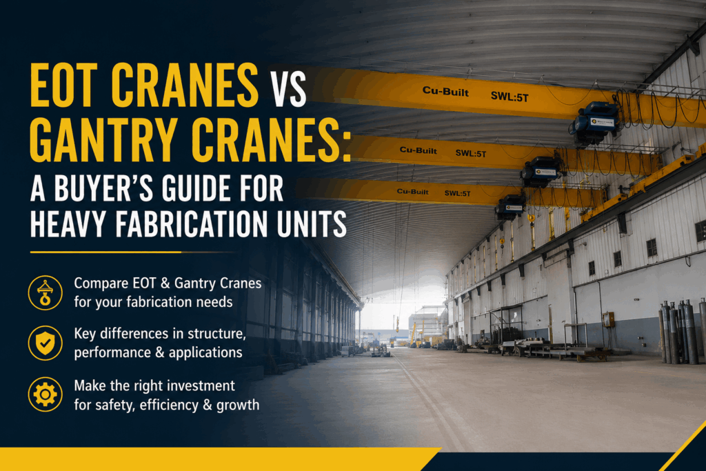
EOT Crane vs Gantry Crane: Which One Does Your Factory Actually Need? (2026 Comparison Guide)

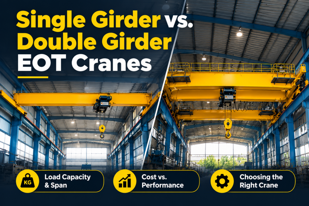
Introduction: The Most Common Crane Selection Mistake in Indian Industry Walk into any manufacturing plant, fabrication yard, or warehouse in India and you will almost certainly find an overhead crane of some kind. And far too often, you will also find the wrong crane for the job — either an EOT crane installed in an outdoor yard where it struggles with environmental exposure, or a gantry crane bolted into a building where it unnecessarily increases structural costs. The difference between an EOT (Electric Overhead Travelling) Crane and a Gantry Crane goes far deeper than how they look. It affects your civil structure requirements, your operating costs, your maintenance burden, and your production capacity for the next 20 years. This guide gives you a clear, no-nonsense comparison — so you walk away knowing exactly which crane type fits your facility, your budget, and your operational needs. What Is an EOT Crane? An EOT Crane (Electric Overhead Travelling Crane) is a fixed overhead crane where the bridge girder is supported by rails mounted on runway beams attached to the building’s structural columns. The crane travels along these elevated rails, covering the full length of the bay. EOT cranes are the backbone of Indian manufacturing — found in steel plants, automobile factories, engineering shops, power plants, and heavy fabrication units across the country. Key Components of an EOT Crane: EOT cranes are manufactured to IS 807 and IS 3177 standards in India, which define design loads, duty classifications (M1 to M8), and safety requirements. �� Explore Cu-Built’s Full EOT Crane Range What Is a Gantry Crane (Goliath Crane)? A Gantry Crane (also called a Goliath Crane) is a crane where the bridge girder is supported by free-standing A-frame legs that travel along ground-level rails. It does not require any building runway structure — the crane is self-supporting. A Semi-Gantry Crane is a hybrid: one side runs on ground rails while the other side is supported on a building column runway — useful when you need outdoor reach on one side and indoor coverage on the other. Gantry cranes are essential in open fabrication yards, shipyards, rail infrastructure projects, precast concrete plants, and wind tower manufacturing facilities — anywhere a building structure either doesn’t exist or can’t support overhead rail loads. �� See Cu-Built’s Gantry and Goliath Crane Range EOT Crane vs Gantry Crane — The Complete Head-to-Head Comparison Comparison Factor EOT Crane Gantry / Goliath Crane Support structure Building runway beams & columns Free-standing A-frame legs on ground rails Best environment Enclosed factory / workshop Open yard, outdoor facilities, large sheds Civil requirement High — building must be designed/rated for crane loads Moderate — only ground rail foundations required Span range 5m to 30m+ 10m to 80m+ Capacity range 1T to 500T 10T to 1,000T+ Installation cost Lower if building already exists Higher upfront (legs + ground rails), but no building load Operational flexibility Fixed to building bay Can span areas outside any building Maintenance access Easier (fixed height) More complex (tall structures) Indoor/Outdoor Primarily indoor Both indoor and outdoor Typical industries Manufacturing, auto, steel, pharma Shipbuilding, wind towers, EPC yards, precast Deep Dive — EOT Crane Types and When to Choose Each Single Girder EOT Crane Uses one main bridge beam supported at each end by end carriages. The hoist hangs below the girder on an underslung trolley. Choose single girder when: Best industries: General engineering, light manufacturing, warehouses, workshops �� Cu-Built Single Girder EOT Cranes Double Girder EOT Crane Uses two parallel bridge beams with the crab trolley running on top rails between them. This provides significantly greater structural rigidity, higher hook height, and higher duty cycle capability. Choose double girder when: Best industries: Steel plants, heavy fabrication, automotive assembly, power generation, oil & gas �� Cu-Built Double Girder EOT Cranes Deep Dive — Gantry Crane Types and When to Choose Each Double Girder Goliath Crane The heaviest-duty gantry configuration — two bridge girders spanning between two tall A-frame leg assemblies. Capable of lifting the most massive loads over the widest spans. Choose when: Wind tower section handling, large vessel lifts, ship section assembly, precast yard stackingCapacity: Up to 1,000 tonnes and beyond for special applications �� Cu-Built Double Girder Goliath Cranes Single Girder Goliath Crane One bridge girder on A-frame legs. More economical than the double girder version for mid-range capacities in semi-open or outdoor environments. Choose when: Fabrication yards up to 100 tonnes, rail and infrastructure projects, material staging areas Semi-Goliath Crane One leg runs on a ground rail; the other side hooks onto an existing building runway. This is the most cost-effective solution when you need to extend coverage from inside a building into an adjacent outdoor area. Choose when: Existing factory with outdoor extension yard, EPC contractors needing flexible coverage�� Cu-Built Semi-Goliath Cranes Crane Safety Standards You Must Know Before Buying Whether you choose an EOT crane or a gantry crane, Indian safety regulations and international standards mandate specific design, installation, and inspection requirements: Cu-Built cranes are designed and manufactured in compliance with IS standards and customer-specified international codes (FEM, DIN, AS standards available on request). Real Industry Applications — Which Companies Use Which Crane Heavy Fabrication & Wind Tower Manufacturing Wind tower plants require the movement of shell sections weighing 30–100 tonnes over large outdoor yards. Goliath gantry cranes with spans of 20–40m are the standard choice. Cu-Built has supplied gantry cranes to wind energy clients including Enercon and Ayana. Automotive Assembly Plants Assembly lines use double girder EOT cranes for engine block handling, body-in-white movement, and tooling changes. Typical capacity: 5T to 50T with M5/M6 duty class for high cycle rates. Oil & Gas Fabrication Yards EPC contractors running open-air pipe spool and pressure vessel fabrication yards use semi-goliath or full goliath cranes for heavy lifts combined with EOT cranes in covered fabrication bays. Steel Melting Shops Double girder EOT cranes with ladle attachments are essential — duty class M7 or M8 for continuous operation, with anti-sway and precision positioning systems. Infrastructure and Construction Precast Plants Gantry cranes with large spans handle precast beam and slab stacking — outdoor environment, ground-level rail operation. Total Cost of Ownership — EOT

welding rotator, pipe welding rotator, self-aligning welding rotator, welding rotator types, vessel fabrication rotator, tank turning rolls, welding rotator selection guide
Uncategorized

How to Choose the Right Welding Rotator for Pipe & Vessel Fabrication: A Complete Buyer’s Guide (2026)

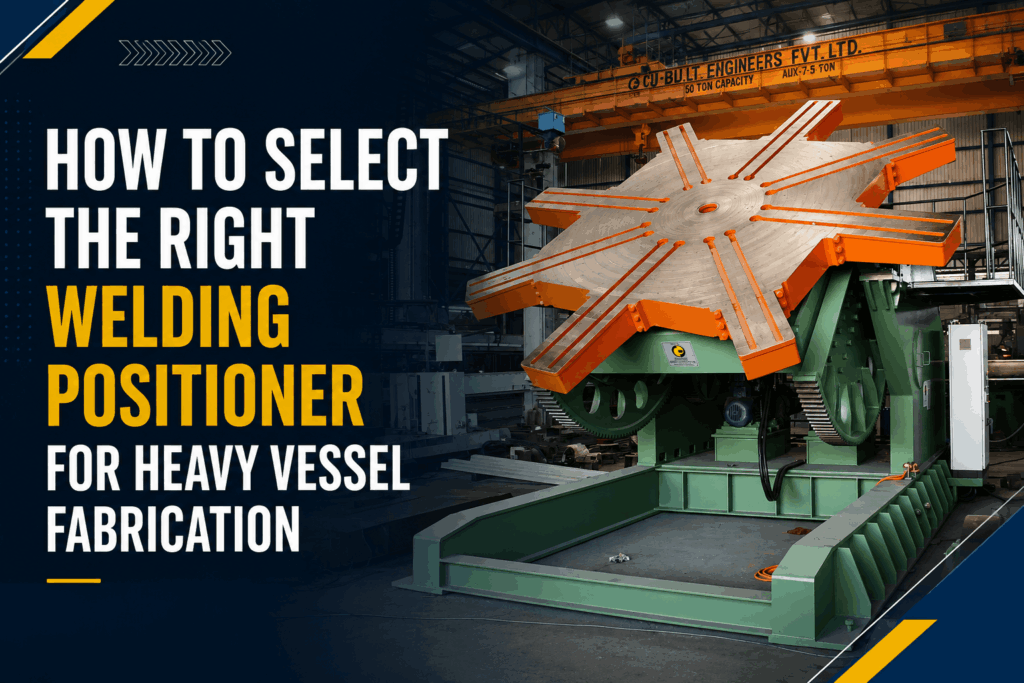
Every year, fabrication shops and heavy manufacturing plants lose thousands of hours — and lakhs of rupees — because they bought the wrong welding rotator for their job. A rotator that can’t handle your workpiece geometry. A drive system that slips under load. Rollers that mark the surface of pressure vessels. These are not small problems — they cause weld defects, rework cycles, project delays, and in some cases, safety incidents. The good news? With the right knowledge, choosing a welding rotator is straightforward. Whether you are fabricating pressure vessels, wind towers, storage tanks, heat exchangers, or large-bore pipework, this complete buyer’s guide walks you through every factor that determines the right welding rotator for your application — load capacity, roller type, drive configuration, and more. Let’s start from the beginning. What Is a Welding Rotator and How Does It Work? A welding rotator (also called a tank turning roll or pipe rotator) is a piece of welding automation equipment designed to rotate cylindrical workpieces — such as pipes, pressure vessels, tanks, and boilers — at a controlled speed during the welding process. Instead of the welder or robot moving around the workpiece, the rotator turns the part beneath a fixed welding torch. This delivers: According to the American Welding Society (AWS), positioning equipment like welding rotators can improve weld quality consistency by up to 30% compared to manual positional welding — a significant gain in heavy fabrication environments. The basic setup consists of drive rolls (powered, to rotate the workpiece) and idle rolls (unpowered, to support and stabilize). More advanced systems add hydraulic adjustment, anti-creep controls, and integrated PLC speed control. The 7 Main Types of Welding Rotators — And When to Use Each One 1. Conventional Type Welding Rotators The most widely used rotator in general fabrication. Conventional rotators have fixed-width roller frames and are best suited for workpieces with consistent diameters. Best for: Storage tanks, standard pipe spools, boilers, rollers with predictable OD rangesCapacity: Typically 5 tonnes to 300 tonnesKey advantage: Simple operation, low maintenance, cost-effective �� Explore Cu-Built’s Conventional Type Welding Rotators 2. Self-Aligning Welding Rotators Self-aligning rotators automatically adjust roller angles to match the diameter and weight of the workpiece — no manual adjustment needed. The rollers pivot to cradle the part correctly every time. Best for: Fabrication shops handling multiple vessel sizes; pressure vessel OEMs; job shopsCapacity: 5 tonnes to 1,000+ tonnesKey advantage: Faster setup, less operator skill required, safer for irregular or tapered shells This is one of the most popular rotator types in India’s growing pressure vessel and oil & gas fabrication sector. �� See Cu-Built’s Self-Aligning Welding Rotators 3. Self-Centering Type Welding Rotators A more advanced variant where rollers automatically center the workpiece along the longitudinal axis. This is critical for applications where precise weld seam tracking is required. Best for: Large-diameter vessels, wind tower can sections, pipeline componentsKey advantage: Eliminates lateral drift during rotation — especially important with SAW (Submerged Arc Welding) processes 4. Pipe Welding Rotators Designed specifically for the dimensions and weights of pipe fabrication. These rotators have a narrower frame width and are optimized for smaller OD ranges typically found in piping work. Best for: Pipe spooling shops, EPC contractors, oil & gas maintenance facilitiesCommon OD range: 50mm to 2,000mm �� View Cu-Built’s Pipe Welding Rotators 5. Hydraulic Shell-to-Shell Fit-Up Rotators These are specialized rotators used to align and fit-up two shell sections before welding begins — a critical step in multi-can vessel manufacturing. The hydraulic system precisely controls end-to-end alignment. Best for: Pressure vessel manufacturers, wind tower fabricators, storage tank plantsKey advantage: Eliminates manual fit-up — dramatically reduces the time between shell rolling and first weld pass 6. Stand Welding Rotators Stand rotators are elevated systems used when the workpiece needs to be positioned at a greater working height — for example, when welding long horizontal vessels on a production line where material handling equipment operates underneath. Best for: Industrial production lines, shipyards, heavy equipment OEMs 7. Blasting and Painting Rotators These are rotators designed not for welding, but for surface preparation and coating. They rotate vessels slowly and uniformly during shot blasting, grit blasting, or paint application — ensuring full 360° coverage. Best for: Pre-treatment shops, tank manufacturers, pressure vessel surface finishing 5 Critical Factors When Selecting a Welding Rotator Before you raise a purchase order, your selection must be based on these five engineering parameters: 1. Maximum Load Capacity (tonnes) This is non-negotiable. Always select a rotator rated for at least 20% above your heaviest anticipated workpiece — this buffer accounts for eccentric loads, dynamic forces during startup, and future production growth. Never operate a rotator at 100% of nameplate capacity. 2. Workpiece Diameter Range (OD) Each rotator model has a minimum and maximum OD it can safely support. Self-aligning rotators offer the widest range. Conventional rotators require manual resetting when the OD changes significantly. Confirm the OD range covers your full product mix, not just today’s largest part. 3. Rotation Speed Range (RPM / mm per minute) Welding processes have very different travel speed requirements: Your rotator must deliver consistent, variable speed across the required range without hunting or slippage — particularly critical when welding with automated torch carriages. 4. Roller Material and Surface 5. Anti-Creep / Anti-Drift Control Heavy workpieces tend to “walk” axially during rotation due to slight misalignment or taper. A quality welding rotator must include an anti-creep mechanism — either mechanical angling of the drive rolls or electronic correction via PLC — to keep the seam under the torch. According to Lincoln Electric’s automation guidelines, axial drift control is one of the top three reasons fabricators experience failed automated welds on rotators. Welding Rotator vs Welding Positioner — What’s the Difference? This is one of the most commonly asked questions in fabrication shops: Feature Welding Rotator Welding Positioner Best for Cylindrical parts (pipes, vessels) Irregular or smaller assemblies Motion Continuous rotation Tilt + rotation (2-axis) Typical workpiece Tanks, boilers, towers Flanges, brackets, small fabrications Weight range 5T to 1,000T+ 0.5T to 200T Integration Works with column & boom Works standalone or with boom For large cylindrical work, rotators are almost always the

Future of Windmill Tower Manufacturing in India
Uncategorized

The Future of Windmill Tower Manufacturing in India: A Green Industrial Revolution

The global shift toward sustainable energy has placed India at the center of a massive industrial transition. As the nation strives to meet its ambitious goal of 500 GW of non-fossil fuel energy capacity by 2030, the Future of Windmill Tower Manufacturing in India has become a focal point for investors, engineers, and policymakers alike. No longer just a secondary component, the wind tower is evolving into a sophisticated piece of engineering designed to support larger turbines and endure harsher environments. The wind energy sector is currently witnessing a paradigm shift. From the implementation of the Production Linked Incentive (PLI) schemes to the emergence of offshore wind projects, India is positioning itself as a global hub for renewable energy hardware. In this blog, we explore the technological advancements, market drivers, and strategic innovations shaping the wind tower industry. The Rising Trajectory of Wind Energy in India India currently ranks fourth globally in installed wind power capacity. However, the “low-hanging fruit” of high-wind sites has largely been tapped. The future of windmill tower manufacturing in India now lies in reaching higher altitudes where wind speeds are more consistent. This necessitates the production of taller, more resilient towers. Manufacturers are moving away from standard tubular steel towers to hybrid models—combining concrete and steel—to reach heights of 140 meters and beyond. This evolution is not just about height; it is about localizing the supply chain to reduce costs and carbon footprints. Key Trends Shaping the Future of Windmill Tower Manufacturing in India 1. Shift Toward Tall Hybrid Towers As turbine capacities increase from 2MW to 5MW+, the structural demands on towers have intensified. Hybrid towers allow for greater stability and height, capturing stronger winds. This shift is driving demand for precision welding and heavy-duty fabrication capabilities. 2. The Offshore Wind Frontier With a coastline spanning over 7,500 km, India’s offshore wind potential is staggering. Manufacturing towers for marine environments requires advanced anti-corrosive coatings and massive structural integrity. The future of windmill tower manufacturing in India will see dedicated coastal manufacturing clusters designed to ship these behemoths directly to sea. 3. Automation in Fabrication Efficiency is the name of the game. Advanced CNC plate cutting machines and automated welding lines are replacing manual processes. This ensures zero-defect manufacturing and speeds up the “time-to-market” for large-scale IPP (Independent Power Provider) projects. Government Policy: The Wind Beneath the Wings The Indian government’s focus on “Atmanirbhar Bharat” has significantly boosted the future of windmill tower manufacturing in India. Policy interventions like the Inter-State Transmission System (ISTS) charges waiver for wind projects and the notification of the National Offshore Wind Energy Policy have created a predictable roadmap for manufacturers. Furthermore, the Ministry of New and Renewable Energy (MNRE) is consistently bidding out capacities, ensuring a steady pipeline of work for fabrication units. According to recent reports by IRENA, India’s commitment to decarbonization is among the most transparent in the developing world, attracting significant Foreign Direct Investment (FDI). Technical Challenges in Modern Tower Manufacturing Manufacturing a wind tower is a feat of heavy engineering. It involves: To address these challenges, companies are adopting Heavy Duty Column and Boom systems that allow for seamless welding of large-diameter cylinders. The Role of CuBuilt in the Wind Energy Ecosystem At CuBuilt, we understand that the future of windmill tower manufacturing in India depends on the quality of the machinery used in the fabrication process. We provide the heavy-duty infrastructure that allows manufacturers to scale their operations. Our Rotators and Rollers are designed to handle the massive weights of modern turbine towers, ensuring precise rotation for high-quality welding seams. By providing world-class fabrication equipment, we enable Indian manufacturers to compete on a global stage, ensuring that “Made in India” wind towers are installed from the North Sea to the Australian Outback. Sustainability in Manufacturing The irony of building green energy components in a high-pollution factory is not lost on the industry. The future of windmill tower manufacturing in India involves adopting “Green Steel” and energy-efficient fabrication processes. Reducing scrap through optimized CNC nesting and using solar-powered welding units are becoming industry standards. Economic Impact and Job Creation The expansion of wind tower plants is a massive job creator. From specialized welders and NDT (Non-Destructive Testing) technicians to logistics experts and structural engineers, the sector is revitalizing industrial hubs in states like Gujarat, Maharashtra, and Tamil Nadu. As per data from Global Wind Energy Council (GWEC), every megawatt of wind energy installed creates nearly 30 job-years of employment across the value chain. Future Outlook: 2026 and Beyond By 2026, we expect to see the first major offshore foundations being laid in the Gulf of Khambhat. This will require a completely different scale of manufacturing. The future of windmill tower manufacturing in India will be characterized by: Partner with CuBuilt for Excellence in Fabrication As the wind energy sector grows, the demand for precision, durability, and scale will only increase. Whether you are setting up a new fabrication unit or upgrading an existing line to meet the demands of the future of windmill tower manufacturing in India, CuBuilt is your strategic partner. Our range of automated welding and cutting solutions is engineered to deliver the performance required for the next generation of renewable energy infrastructure. Contact CuBuilt today to explore our heavy-duty fabrication solutions and lead the Indian wind revolution. Frequently Asked Questions (Q&A) Q1: What is the average height of a windmill tower in India?  Currently, most towers range between 80 to 120 meters. However, the trend is moving toward 140-160 meters to capture higher wind speeds. Q2: Why is the “Make in India” initiative important for wind towers?  It reduces the cost of logistics, which can account for up to 20% of the total tower cost, and ensures that the infrastructure is built to suit local climatic conditions. Q3: What materials are used in the future of windmill tower manufacturing in India?  While S355 grade steel remains the standard, we are seeing a rise in high-strength concrete for hybrid towers and advanced

Uncategorized

Top Welding Automation Trends in India for 2026: The Future of Manufacturing

The Indian manufacturing sector is currently undergoing a seismic shift. As we move deeper into the decade, the integration of advanced technology into traditional workflows is no longer a luxury—it is a necessity for survival. For fabrication shops and heavy industries, staying updated on the Top Welding Automation Trends in India for 2026 is the key to maintaining a competitive edge in a global market. With the “Make in India” initiative reaching new heights, the demand for precision, speed, and cost-effectiveness has made manual welding a bottleneck of the past. At Cubuilt, we have witnessed firsthand how automation transforms production lines from labor-intensive hubs into streamlined, high-output powerhouses. Whether you are in automotive, aerospace, or structural engineering, understanding these trends will help you navigate the complexities of modern industrial requirements. 1. The Rise of Collaborative Robots (Cobots) in Welding One of the most significant Top Welding Automation Trends in India for 2026 is the widespread adoption of Collaborative Robots, or “Cobots.” Unlike traditional industrial robots that require massive safety cages and specialized programming, Cobots work alongside human operators. In the Indian context, where skilled welders are increasingly difficult to find, Cobots fill the gap by handling repetitive, high-volume tasks. These machines are designed with sensitive sensors that allow them to stop instantly if they contact a human, ensuring a safe hybrid workspace. Key Benefits of Cobots: 2. Artificial Intelligence and Machine Learning Integration AI is no longer just for software companies. By 2026, AI-driven welding systems will be standard in high-end Indian manufacturing. These systems use machine learning algorithms to analyze weld data in real-time, adjusting parameters like voltage, wire feed speed, and travel speed on the fly to compensate for irregularities in the workpiece. This trend focuses on “First Time Right” manufacturing. By predicting potential defects before they happen, companies can significantly reduce scrap rates and rework costs. 3. Advanced Laser Welding Systems While MIG and TIG remain staples, Fiber Laser Welding is set to dominate the Top Welding Automation Trends in India for 2026. Laser welding offers unparalleled speed and a much smaller Heat Affected Zone (HAZ), which is critical when working with thin materials or exotic alloys. India’s push toward Electric Vehicle (EV) manufacturing is a primary driver for this. The delicate nature of battery packs and lightweight aluminum frames requires the precision that only automated laser systems can provide. You can explore our range of specialized welding SPM to see how laser integration is changing the game. 4. Industry 4.0 and IoT-Enabled Welding Power Sources The concept of the “Smart Factory” is becoming a reality in industrial hubs like Pune, Chennai, and Gurgaon. In 2026, welding power sources are no longer isolated machines; they are IoT (Internet of Things) nodes. What does IoT in welding look like? 5. Adoption of Multi-Process Automated Cells Flexibility is the theme for 2026. Instead of having a single machine for a single task, Indian manufacturers are investing in Multi-Process Automated Welding Cells. These cells can switch between MIG, TIG, and Plasma cutting within the same footprint. This trend is particularly relevant for job shops that handle diverse contracts. By using modular welding rotators and positioners, a single cell can handle everything from small pipe joints to massive pressure vessels. 6. Green Welding: Sustainability in Automation Environmental regulations in India are tightening. Sustainability is a core pillar of the Top Welding Automation Trends in India for 2026. Automated systems are significantly more energy-efficient than manual setups. They produce less fume, use consumables more effectively, and reduce the overall carbon footprint of the plant. High-efficiency inverter-based power sources integrated with robotic arms ensure that power is only consumed during the actual arc-on time, leading to massive savings on utility bills. 7. Enhanced Virtual Reality (VR) Training for Operators As automation grows, the role of the human operator shifts from “welder” to “robot technician.” To bridge the skill gap, VR-based training has become an essential trend. It allows new workers to practice on automated interfaces in a risk-free environment, saving on material costs during the learning phase. To truly grasp the Top Welding Automation Trends in India for 2026, one must look at the broader scope of Industrial Robotics and Smart Manufacturing. In India, the Robotic Welding Market is expected to grow by double digits, driven by the need for Precision Engineering and Automated Quality Control. Companies are no longer just buying a machine; they are investing in Digital Transformation of their shop floors. This involves Welding Data Analytics and the implementation of Cloud-based Fabrication Management. Why Choose Cubuilt for Your Automation Journey? Transitioning to automation can be daunting. At Cubuilt, we specialize in providing end-to-end solutions tailored to the unique challenges of the Indian industrial landscape. From Column and Boom setups for heavy fabrication to intricate robotic cells, our engineering team ensures that your investment yields the highest ROI. We don’t just sell machines; we build partnerships. Our systems are designed to be future-proof, ensuring that as the Top Welding Automation Trends in India for 2026 evolve, your facility remains at the cutting edge of technology. Boost Your Production with Cubuilt’s Expert Solutions Are you ready to revolutionize your manufacturing process? Don’t let outdated manual processes hold your business back. Whether you need to increase your throughput, improve weld quality, or solve labor shortage issues, Cubuilt has the expertise to guide you. Contact our automation experts today for a free plant assessment and custom quotation! Frequently Asked Questions (Q&A) Q1: What is the biggest advantage of robotic welding for Indian SMEs? The biggest advantage is consistency. Unlike manual welding, which is subject to human fatigue, a robot performs the same high-quality weld every single time, 24/7. This reduces waste and ensures your products meet international standards like those set by the American Welding Society (AWS). Q2: Is welding automation too expensive for small-scale industries? While the initial investment is higher, the ROI is usually achieved within 12 to 24 months through increased speed, reduced rework, and lower consumable waste. 2026 models

Scroll to Top