Welding Rotator: Types, Applications, and Benefits for Industrial Manufacturing
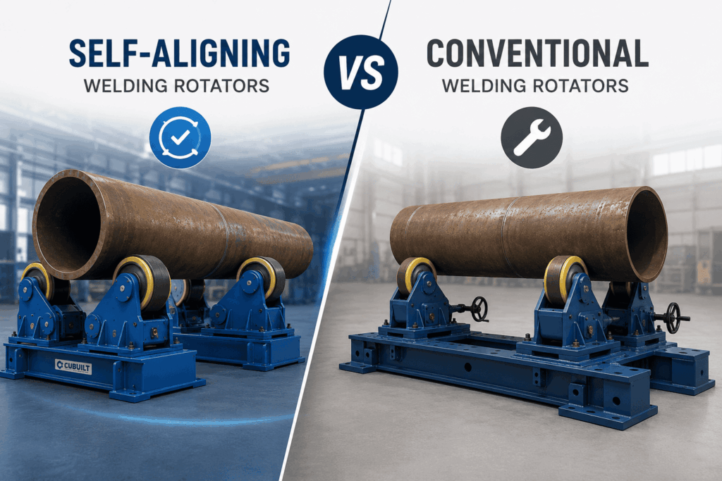
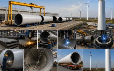
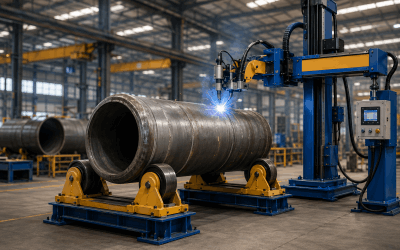
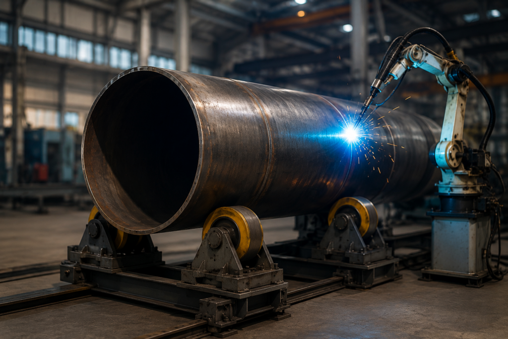
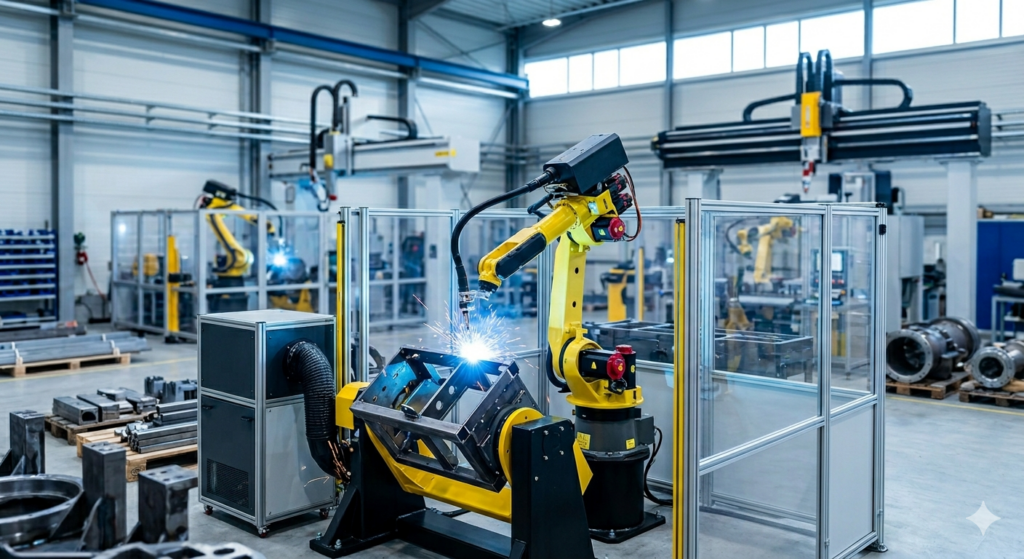
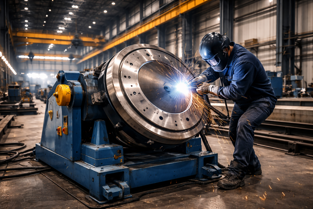
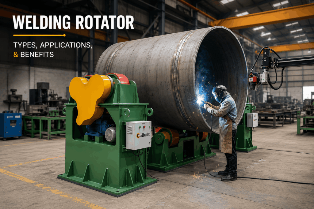
The demands of modern industrial manufacturing require precision, speed, and uncompromising safety. When dealing with massive cylindrical workpieces—such as pressure vessels, storage tanks, pipelines, and heavy structural columns—manual manipulation is not only inefficient but highly hazardous. This is where the welding rotator becomes an indispensable asset on the factory floor. A welding rotator is a specialized piece of heavy-duty engineering equipment designed to rotate cylindrical or conical objects during welding and fabrication processes. By maintaining a constant, controlled speed, these machines allow welding torches (whether manual, semi-automatic, or fully automatic) to remain stationary while the workpiece rotates uniformly. This configuration ensures smooth, deep-penetration welds that meet rigorous quality standards. Integrating an industrial welding rotator into your production line eliminates the need for cranes, forklifts, and complex rigging systems to turn heavy loads. As structural fabricators face tightening deadlines and stricter compliance standards, choosing the right welding rotator machine is the ultimate key to maximizing throughput, eliminating operational bottlenecks, and protecting skilled technicians. What is a Welding Rotator? At its core, a welding rotator—often referred to globally as welding turning rolls—consists of a motorized drive unit and one or more idler units. The drive unit houses an electric motor and gearbox that powers heavy-duty wheels (usually coated in polyurethane, rubber, or made entirely of steel) to turn the workpiece. The idler units provide additional structural support along the length of the vessel or pipe. By providing a stable, motorized rotating platform, this fabrication welding equipment ensures that circumferential seams are welded continuously in the ideal flat downhand position (1G/PA). Welding in the flat position yields superior metallurgical properties, better bead aesthetics, and a significantly lower risk of defects like slag inclusions, porosity, or lack of fusion. Types of Welding Rotators Used in Manufacturing Different fabrication projects involve varying diameters, weights, and wall thicknesses. To accommodate these diverse manufacturing demands, a premium welding rotator manufacturer offers several distinct configurations: 1. Conventional Type Welding Rotator The conventional type welding rotator is engineered with fixed wheel centers that must be manually adjusted to accommodate different workpiece diameters. The operator moves the roller housings along the base frame using bolt slots or lead screw mechanisms. 2. Self Aligning Welding Rotator A self aligning welding rotator features independent wheel assemblies that automatically pivot and adjust their orientation to match the exact diameter of the workpiece as it is lowered onto the bed. 3. Self Centering Welding Rotator The self centering welding rotator utilizes a synchronized lead screw or mechanical linkage system to move both roller beds simultaneously toward or away from the center line. This ensures that the exact center axis of the cylindrical workpiece remains constant, regardless of its diameter. This feature is highly advantageous when integrating the rollers with fixed welding columns and booms. 4. Pipe Welding Rotator Tailored specifically for smaller diameters and rapid cycle times, a pipe welding rotator is optimized for cross-country pipeline construction, refinery piping systems, and mechanical workshop plumbing. These systems typically utilize high-traction polyurethane rollers to prevent scratching or damaging polished surfaces on exotic materials like stainless steel or duplex alloys. 5. Hydraulic Shell to Shell Fit Up Welding Rotator When aligning two separate cylindrical shells for tack welding, a standard roller is not enough. A hydraulic shell to shell fit up welding rotator incorporates hydraulic cylinders capable of shifting the rollers vertically, horizontally, and independently. This allows operators to perfectly align the joint faces, correct eccentricities, and eliminate “hi-lo” structural mismatches prior to running the main weld passes. Technical Comparison of Core Turning Roll Configurations Feature Conventional Type Rotator Self Aligning Rotator Self Centering Rotator Diameter Adjustment Manual (Bolts/Lead Screw) Automatic (Pivoting Rockers) Synchronized Mechanical Ideal Load Range Up to 1000+ Tons Up to 500 Tons Up to 200 Tons Setup Time Moderate Zero Low Thin-Wall Support Standard Excellent (4-point contact) Good Automation Compatibility Good Excellent Superior (Fixed Centerline) Key Benefits of Implementing an Automatic Welding Rotator Investing in an automatic welding rotator yields substantial financial and operational returns. If your facility is trying to decide how does a welding rotator improve welding efficiency, consider these critical advantages: 1. Unmatched Weld Quality and Defect Reduction When operators attempt to weld large cylindrical seams manually without a rotator, they must constantly stop to reposition the workpiece. Every stop-and-start introduces a high vulnerability point for defects like lack of penetration or porosity. A motorized roller ensures continuous, uninterrupted rotation, enabling consistent arc voltage and travel speed. 2. Exponential Productivity Gains By eliminating the reliance on overhead factory cranes to turn vessels step-by-step, non-productive handling time is reduced by up to 70%. Welders can keep their torches lit for longer durations, greatly increasing arc-on time and overall deposition rates. 3. Enhanced Workplace Safety Suspended heavy loads are one of the most prominent safety hazards in structural fabrication shops. Utilizing a low-profile, floor-mounted heavy duty welding rotator keeps massive steel vessels securely cradled at ground level, minimizing crane lifts and mitigating the risk of catastrophic catastrophic workplace accidents. 4. Reduced Fatigue for Professional Welders Working over overhead zones or maintaining awkward bodily positions for hours causes rapid welder fatigue, which degrades weld quality over a shift. Rotators place the weld joint directly in front of the worker at an ergonomic height, allowing them to focus strictly on puddle control. Industrial Applications Across Sectors From minor industrial piping networks to massive aerospace assemblies, high-capacity turning rolls are utilized across a vast spectrum of critical industrial landscapes: Selecting the Best Welding Rotator for Heavy Fabrication Industries Choosing the correct equipment requires evaluating more than just the gross weight of your heaviest workpiece. To source the best welding rotator for heavy fabrication industries, your engineering team must analyze the following parameters: Elevate Your Production with CuBuilt’s Engineering Solutions At CuBuilt Engineers, we specialize in designing and manufacturing top-tier industrial automation systems that tackle your toughest fabrication challenges. As a globally recognized welding rotator manufacturer, our equipment is built to withstand rugged foundry and shop floor conditions while delivering pinpoint accuracy. Whether your facility