Introduction: India’s Wind Energy Boom Is Creating a Manufacturing Gold Rush
India has set one of the most ambitious renewable energy targets in the world: 500 GW of non-fossil fuel energy capacity by 2030, with wind power expected to contribute 140 GW of that total. As of 2026, the country is accelerating wind project commissioning at a pace that is creating unprecedented demand for one critical component: the wind tower itself.
Every wind turbine — onshore or offshore — requires a steel tower typically standing 80 to 160 metres tall, built from rolled and welded steel plate sections called “cans” or “shell sections.” These towers weigh 200 to 500 tonnes each. And with India targeting thousands of new turbines over the next five years, the demand for tower fabrication capacity is growing faster than the industry can build it.
This creates a significant business opportunity for steel fabricators, EPC contractors, and industrial manufacturers who are ready to invest in wind tower manufacturing infrastructure.
This guide covers everything you need to know — the complete fabrication process, the specific equipment required at each stage, the quality standards involved, and why 2026 is the right window to establish wind tower manufacturing capability in India.
H2: India’s Wind Energy Market — The Numbers Behind the Opportunity
Before diving into manufacturing, let’s establish the scale of the commercial opportunity.
The Ministry of New and Renewable Energy (MNRE) has allocated over 50 GW of new onshore wind capacity under various tenders and schemes currently in execution. Each 2 MW turbine (a common size) requires one tower. That’s 25,000+ new wind towers for just the currently tendered capacity.
The Global Wind Energy Council (GWEC) ranked India as the 4th largest wind market globally in its 2025 report — and projects India’s annual installation rate to double by 2027.
States like Gujarat, Rajasthan, Karnataka, and Maharashtra are seeing the highest project density — which means tower fabrication facilities located in or near these states have a structural logistics advantage.
Key market facts:
- Average tower height trend: moving from 90m to 120m+ (taller = more steel = higher fabrication value)
- Local content requirements under Make in India policy: pushing tower sourcing towards domestic manufacturers
- Tower export potential: India is increasingly competitive for supplying towers to Southeast Asia and Middle East markets
For fabricators with the right equipment and quality certifications, wind tower manufacturing is one of the highest-value, most defensible positions in India’s industrial supply chain for the decade ahead.
H2: What Does a Wind Tower Look Like? — Understanding the Product You’re Manufacturing
A modern onshore wind tower is a tapered tubular steel structure built in sections. Here’s the basic anatomy:
- Bottom section (base can): Largest diameter, thickest wall — typically 4,000–5,000mm OD, 25–40mm wall thickness
- Mid sections: Progressively smaller diameter cans, 3,000–4,000mm OD, 18–28mm wall thickness
- Top section (nacelle section): Smallest diameter, connecting to the turbine nacelle, 2,000–3,000mm OD
- Flange rings: Heavy forged or fabricated rings welded to each can end, providing the bolted connection between sections
- Internal platforms, ladders, cable trays: Installed inside the tower during assembly
A 120-metre hub-height tower typically consists of 5–7 shell sections (cans), with total steel weight of 350–450 tonnes. Each can is 20–30 metres long.
H2: The Complete Wind Tower Fabrication Process — Stage by Stage
Stage 1: Steel Plate Procurement and Incoming Inspection
Wind tower manufacture begins with high-strength structural steel plate — typically S355, S420, or S460 grade to EN 10025 standards, or equivalent IS/ASTM grades approved by the turbine OEM.
Incoming plate inspection covers dimensional verification, material certification review, ultrasonic testing (UT) for internal laminations, and surface condition check. This stage sets the quality foundation for everything that follows.
Stage 2: Plate Edge Preparation (Bevelling and Profiling)
Before rolling, each plate edge must be precision-bevelled to the required weld joint geometry. This is done using CNC plasma or oxy-fuel cutting machines with automatic bevelling heads — or dedicated bevelling machines for straight edges.
For longitudinal seam welds, a double-V (X) or single-V bevel is typical. For circumferential seam welds (connecting cans), precise bevelling is essential to achieve the required weld quality in multi-pass SAW joints.
Stage 3: Plate Rolling — Forming the Shell Section
The bevelled plate is rolled into a cylindrical shell using a 3-roll or 4-roll CNC plate rolling machine. For large-diameter tower sections:
- Bottom can (Ø4,500mm, 40mm wall): Requires a rolling machine with capacity of 500T–1,000T rolling force
- Top cans (Ø2,000mm, 16mm wall): Can be handled by smaller capacity rolling machines
Tack welding holds the shell geometry before the longitudinal seam is completed. Dimensional control during rolling — roundness, diameter, and straightness — directly determines how accurately sections will mate during erection, which is critical for load-bearing performance.
Stage 4: Longitudinal Seam Welding
With the can section tack-welded into shape, the longitudinal (vertical) seam weld is completed. This is typically done using:
- Submerged Arc Welding (SAW): The primary process — high deposition rate, excellent quality, fully mechanised
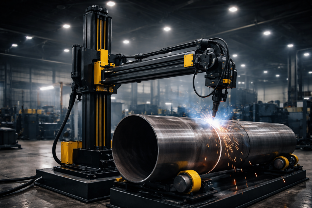
- A welding column and boom positions the SAW torch for the inside pass; the outside pass is completed after back-gouging and grinding
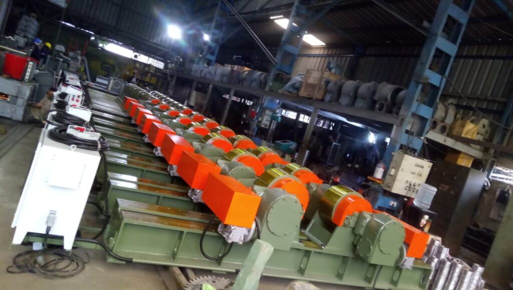
The can is held in position using stand rotators or welding rotators to maintain the seam in a consistent flat position during welding.
Cu-Built Welding Column and Boom Systems for Tower Fabrication
Stage 5: Flange Welding and Fitment
Heavy flange rings are welded to each end of the can section. This is among the most demanding welding operations in tower fabrication because:
- Flanges are typically 100–180mm thick forged steel
- Weld joint is subject to the highest fatigue loads in the assembled tower
- Dimensional tolerance on flange flatness and perpendicularity is typically ±1mm over the full diameter
Welding rotators with hydraulic fit-up capability are used to position and align the flange to the shell before and during welding. Precise concentricity is critical.
Cu-Built Hydraulic Shell-to-Shell and Fit-Up Welding Rotators
Stage 6: Circumferential Seam Welding (Shell-to-Shell Join)
Where multiple plate sections are joined to form a single long can, the circumferential (girth) seam is welded using a welding rotator + column and boom combination. The can rotates while the SAW torch remains stationary.
This is where welding automation delivers the clearest quality advantage over manual methods — the 1G flat position, consistent travel speed, and controlled heat input produce highly repeatable weld quality essential for fatigue-loaded structures.
Stage 7: Non-Destructive Testing (NDT)
Every structural weld in a wind tower is tested before the section leaves the fabrication bay:
- Ultrasonic Testing (UT): Full volumetric inspection of all longitudinal and circumferential welds
- Magnetic Particle Testing (MPI): Surface and near-surface inspection
- Visual Inspection (VT): Dimensional and surface condition verification
- Dimensional survey: Roundness, diameter, length, flange flatness, and bolt hole position
Third-party inspection bodies — DNV GL, Lloyd’s Register, TUV, or Bureau Veritas — certify compliance to the project-specific ITP (Inspection and Test Plan).
Stage 8: Surface Treatment — Blasting and Painting
External surfaces are shot-blasted to SA 2.5 standard (near-white metal) and coated with a multi-layer paint system to the OEM’s specification — typically primer + intermediate + topcoat with a total DFT of 240–320 microns.
Blasting and painting rotators are used to rotate the can sections at a consistent, slow speed during both surface preparation and paint application — ensuring uniform treatment across the full 360° surface.
Stage 9: Internal Fitout and Final Assembly
After painting, internal components are installed: access platforms, ladder systems, cable trays, aviation warning light cabling, and internal coating. The completed sections are then trial-assembled (dry fit) to verify bolt hole alignment before dispatch.
H2: Key Equipment Required for a Wind Tower Manufacturing Plant
| Stage | Equipment | Cu-Built Solution |
| Longitudinal seam | Column & Boom + Stand Rotator | ✅ Available |
| Girth seam | Welding Rotator (self-aligning, large capacity) | ✅ Available |
| Flange fitup & welding | Hydraulic Fit-Up Rotator + Head/Tail Stock | ✅ Available |
| Blasting & painting | Painting/Blasting Rotator | ✅ Available |
| Yard handling | Goliath/Gantry Crane (30T–200T) | ✅ Available |
| Indoor bay handling | Double Girder EOT Crane | ✅ Available |
| Section transport | Motorized Transfer Trolleys | ✅ Available |
Cu-Built can supply the complete equipment package for a wind tower manufacturing plant — from welding automation to material handling — as a turnkey solution, including layout planning, installation, and commissioning.
Explore Cu-Built’s Wind Tower Manufacturing Solutions
H2: Quality Certifications Required for Wind Tower Fabrication in India
To supply towers to major wind OEMs (Vestas, Siemens Gamesa, Windworld, Enercon, GE Vernova), fabricators in India must typically hold:
- ISO 9001:2015 — Quality Management System
- ISO 3834-2 or ISO 3834-3 — Welding quality requirements for fusion welding
- EN 1090-2 — Execution of steel structures (required for European OEM supply)
- IIW or CSWIP Welding Coordinator — Qualified welding supervision
- NABL-accredited NDT — For in-house UT and MPI testing
Cu-Built works with clients to identify and plan the certification pathway required for their target market.
H2: Why 2026 Is the Right Time to Establish Wind Tower Manufacturing Capacity
- Order books are full: Major wind OEMs in India are tendering multi-year supply agreements for tower sections. Early entrants with certified facilities have the strongest position.
- Make in India tailwinds: Policy actively incentivises domestic tower fabrication over imports.
- Infrastructure window: Rail and port logistics for tower transport are improving — widening the viable supply radius from fabrication locations.
- Skilled welder availability: The window to recruit and train certified welding teams is narrower each year. Building your workforce now, alongside your equipment investment, creates a durable competitive advantage.
H2: Ready to Build India’s Next Wind Tower Manufacturing Facility?
Cu-Built Engineers has supplied welding automation and material handling equipment to wind tower plants serving Enercon, Ayana, and ReNew Power. Our engineering team understands the specific demands of tower fabrication — the tolerances, the inspection requirements, the production flow, and the handling challenges.
Whether you are starting from greenfield or expanding an existing fabrication facility, Cu-Built can design and deliver the complete equipment package to get you producing towers.
Talk to our team. Get a plant layout, equipment list, and capital cost estimate within 5 working days.
Contact Cu-Built for Wind Tower Manufacturing Setup
+91 97300 89705 | sales@cubuilt.com
Plot No. 149, MIDC Bhosari, Pune – 411026
Also explore: