The global move toward sustainable energy has increased demand for utility-scale wind power projects. To capture higher wind velocities, modern turbines require taller, stronger, and more resilient support structures. Behind every reliable turbine lies a sophisticated production setup engineered by top wind turbine tower manufacturers.
Fabricating a tubular windmill tower requires precision engineering, specialized machinery, and adherence to strict quality benchmarks. This comprehensive guide explores essential machinery, structural fabrication phases, and quality management protocols used in modern wind mill tower production facilities.
The Strategic Role of Wind Turbine Tower Manufacturers
Utility-scale wind turbines operate under severe dynamic loads, thermal fluctuations, and aerodynamic stresses. The supporting structure must absorb fatigue cycles continuously over a 20-to-25-year operational lifespan. Because of these demands, wind turbine tower manufacturers must maintain strict metallurgical and structural control.
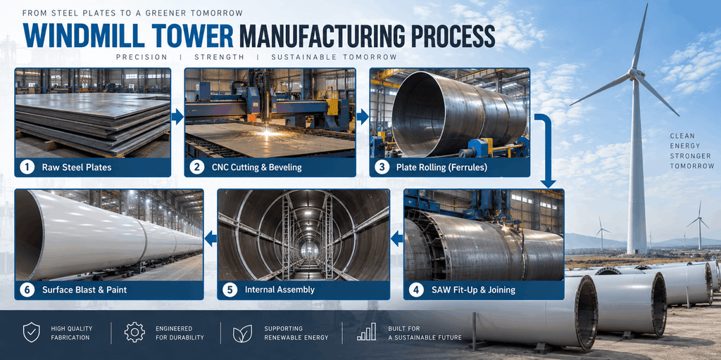
Fabrication facilities rely on advanced welding automation and heavy-duty material handling setups. Modern production units replace manual operations with automated equipment to increase throughput, limit heat-affected zones (HAZ), and meet international standards such as ISO 9001 quality management.
Key Equipment in a Windmill Tower Production Line
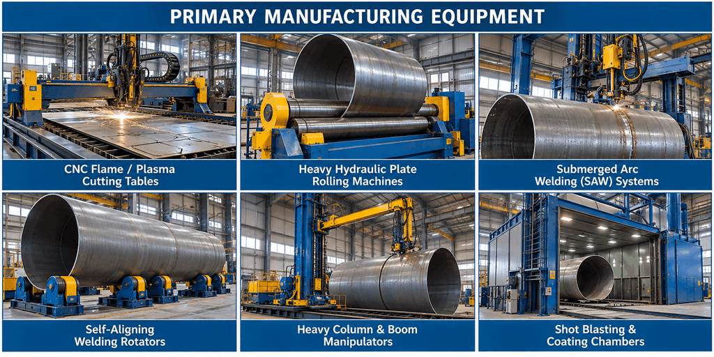
A high-capacity windmill tower plant uses customized machinery designed to process heavy structural steel. Operating at this scale requires precise machinery at every production stage.
1. High-Precision CNC Cutting and Edge Beveling Systems
Production starts with heavy structural steel plates. Multi-torch CNC oxy-fuel or high-definition plasma cutting tables slice raw sheets into precise geometric layouts. Mechanical edge beveling tools create specialized V, double-V, or X-groove profiles that allow full-penetration welding on thick sections.
2. Heavy Hydraulic Plate Rolling Machines
Steel plates move to hydraulic 3-roll or 4-roll bending machines to form individual cylindrical or conical rings called ferrules. These rolling systems apply thousands of tons of force to bend high-yield steel without causing internal micro-cracks or thickness variations.
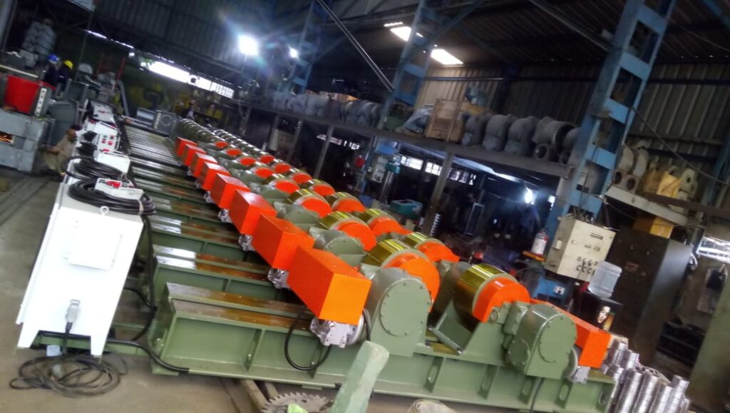
3. Specialized Turning Rolls and Fit-Up Rotators
Once rolled, single ferrules are transferred onto specialized fit-up rotators. Hydraulic alignment rollers adjust the spatial alignment of adjacent shells, ensuring concentricity before longitudinal and circumferential joining. Modern self-aligning rotators automatically adjust to diameter changes along tapered conical sections.
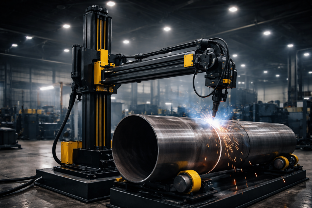
4. Automated Submerged Arc Welding (SAW) Columns and Booms
Joining heavy steel sections requires automated Submerged Arc Welding (SAW) systems. Heavy-duty welding column and boom manipulators position SAW heads inside and outside the tower shell. Single-pass or multi-pass tandem arc configurations deliver deep weld penetration with minimal defect rates, maintaining mechanical properties across long seam lines.
5. High-Capacity Material Handling: Overhead Cranes and Transporters
Moving components weighing up to 100 tons requires reliable lifting infrastructure. Facilities deploy Double Girder EOT Cranes, gantry systems, and motorized transfer trolleys to shift heavy segments safely between preparation, welding, painting, and storage zones.
Step-by-Step Wind Tower Manufacturing Process
Converting flat structural steel plates into a finished utility-scale wind mill tower follows a structured workflow:
Phase 1: Plate Profiling and Ferrule Rolling
Plates undergo ultrasonic testing to check for internal laminations before cutting. After CNC profiling, plates enter the rolling mill to form individual cylindrical or conical ferrules. Precision measuring systems verify roundness and dimensional tolerances across both ends.
Phase 2: Longitudinal Seam Welding
Rolled ferrules move to dedicated longitudinal welding stations. SAW units weld the seam internally and externally. Run-on and run-off tabs maintain arc stability across the entire length, preventing edge defects.
Phase 3: Ring Assembly and Circumferential Welding
Multiple ferrules align end-to-end on fit-up rotators. Specialized manipulators complete circumferential girth welds to form longer structural segments, typically 20 to 30 meters long. Automated seam trackers guide the torch to ensure uniform weld bead geometry.
Phase 4: Heavy Flange Attachment
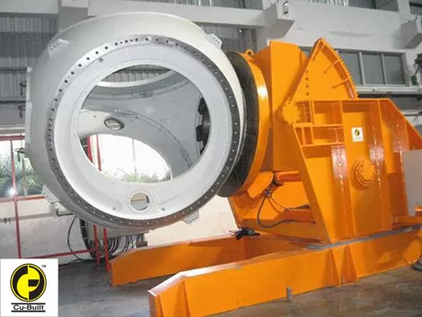
Heavy forged steel flanges connect the tower sections on site. These flanges must be aligned square to the tower’s longitudinal axis. High-capacity positioners hold flanges in place during preheating and full-penetration welding.
Phase 5: Surface Finishing and Corrosion Protection
Wind structures often face harsh marine or atmospheric conditions. Assemblies undergo automated centrifugal shot blasting to achieve an SA 2.5 or SA 3 surface finish. Climate-controlled spray booths then apply multi-coat protection systems, such as zinc-rich epoxy primers and polyurethane topcoats, following standards like ISO 12944 corrosion protection guidelines.
Phase 6: Outfitting Internal Components
After curing, sections move to internal assembly lines. Technicians install internal platforms, access ladders, safety cables, lighting systems, and high-voltage electrical busbars. Outfitting sections in the factory reduces installation time and costs on site.
Heavy Fabrication for Infrastructure and Wind Energy Requirements
Engineering structures for modern renewable energy projects requires robust heavy fabrication for infrastructure. Turbine components must withstand dynamic mechanical stresses, environmental forces, and structural loads over decades of continuous operation.
When building heavy wind energy components, manufacturers balance structural mass with transportation limitations. Onshore logistics cap base section diameters near 4.5 to 5 meters, requiring precise conical designs to maximize height while remaining within transit clearances.
Technical Comparison: Onshore vs. Offshore Tower Production Lines
Manufacturing requirements differ significantly between onshore and offshore wind farms. Offshore environments demand thicker materials, larger diameters, and enhanced surface protection to resist marine exposure.
| Parameter / Feature | Onshore Wind Turbine Mast Manufacturing | Offshore Heavy Wind Energy Components |
| Typical Plate Thickness | 12 mm – 50 mm | 40 mm – 100+ mm |
| Section Base Diameters | Up to 4.5 – 5.0 meters (Road limits) | 6.0 to 10.0+ meters |
| Total Structure Weight | 150 – 350 Metric Tons | 600 – 1,500+ Metric Tons |
| Corrosion Standard | ISO 12944 C3 to C4 | ISO 12944 C5-M / CX (Marine) |
| Material Grade | S355J2+N / S355ML | S355ML / S460ML (Offshore high-yield) |
| Handling Equipment | 50–100 Ton EOT Cranes | 200–500 Ton Goliath Cranes / SPMTs |
Critical Quality Standards and NDT Protocols for Production Lines
Structural integrity depends on rigorous quality assurance at every stage of the wind turbine mast manufacturing process. Unchecked defects can cause catastrophic joint failures under wind loads.
1. Dimensional Accuracy and Ovality Control
Individual shell sections must maintain tight dimensional tolerances. Laser trackers monitor diameter variations, ferrule ovality, and flange face flatness to prevent assembly issues during field erection.
2. Comprehensive Non-Destructive Testing (NDT)
Facilities run rigorous NDT programs on primary structural welds:
- Ultrasonic Testing (UT & PAUT): Detects internal flaws, lack of fusion, and porosity in thick plate welds.
- Magnetic Particle Inspection (MPI): Finds surface and near-surface cracks along high-stress weld boundaries.
- Radiographic Testing (RT): Evaluates weld integrity at complex T-joint intersections.
3. Surface Preparation and Coating Thickness Validation
Coating systems must resist humidity, UV radiation, and salt spray. Quality technicians use digital gauge tools to verify environmental parameters, surface roughness profiles, and Dry Film Thickness (DFT) across all applied layers.
Future Trends in Industrial Tower Fabrication Automation
The wind energy sector continues to adopt digital tools to improve output and consistency in industrial tower fabrication. Advanced manufacturing trends include:
- Robotic SAW Integration: Automated systems use vision sensors to adjust arc parameters in real time based on groove geometry.
- Digital Twin Line Monitoring: Sensors track rotator speed, heat input, and weld parameters, feeding data into factory-wide control networks.
- Narrow-Gap SAW Welding: Optimized bevel angles reduce filler metal consumption and cycle times on thick steel plates.
Upgrade Your Windmill Tower Production Infrastructure with Cu-Built
Scaling your fabrication capabilities requires equipment designed for modern energy infrastructure. Cu-Built Engineers designs and manufactures high-performance welding automation systems, heavy-duty turning rolls, column and boom manipulators, and customized material handling equipment.
Since 2011, Cu-Built has delivered turnkey heavy fabrication setups engineered to meet strict international quality standards. Explore our specialized Windmill Tower Manufacturing Equipment or consult our automation team to optimize your plant’s throughput and welding precision.
Frequently Asked Questions (Q&A)
Q1: What primary equipment is required for a modern windmill tower manufacturing line?
A complete production line requires CNC plate cutting systems, heavy hydraulic plate rollers, fit-up turning rotators, automated Submerged Arc Welding (SAW) columns and booms, shot blasting booths, and high-capacity overhead cranes.
Q2: Why is Submerged Arc Welding (SAW) preferred for wind turbine tower fabrication?
SAW provides deep weld penetration, high deposition rates, and consistent weld quality across thick structural steel. It minimizes internal defects and meets strict non-destructive testing (NDT) criteria.
Q3: What non-destructive testing (NDT) methods are used on wind turbine towers?
Quality protocols use Ultrasonic Testing (UT/PAUT) for internal volumetric checks, Magnetic Particle Inspection (MPI) for surface cracks, and Radiographic Testing (RT) for critical joint intersections.
Q4: How do onshore and offshore wind tower manufacturing lines differ?
Offshore towers use thicker steel plates, larger base diameters, and specialized multi-layer paint systems to handle harsh marine environments and heavy mechanical loads.
Q5: How do turning rolls and rotators improve welding efficiency?
Rotators spin cylindrical tower sections at precise, controlled speeds. This allows SAW heads to weld circumferential seams continuously in the flat down-hand position, improving weld quality and reducing cycle times.