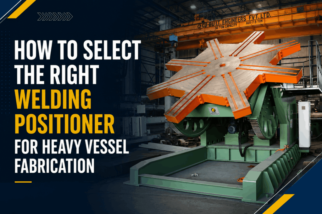
Heavy vessel fabrication demands uncompromising structural integrity, exact geometric precision, and total operator safety. Whether manufacturing high-pressure industrial reactors, storage tanks, or offshore energy boilers, your choice of heavy fabrication equipment dictates overall project efficiency. At the core of every modern high-throughput facility sits an essential machine: the welding positioner.
Using a specialized welding positioner machine enables shop managers to convert complex multi-axis welds into simple, down-hand joint configurations. However, choosing the incorrect positioner setup risks severe equipment strain, costly joint defects, and hazardous shop floor accidents.
This guide details how to select the right welding positioner for heavy vessel fabrication. We will explore essential load metrics, drive systems, positioner configurations, safety integrations, and shop workflow optimization.
Understanding the Fundamentals of Heavy Vessel Welding Positioning
Before choosing equipment for massive cylindrical workpieces, you must understand how workpiece manipulation changes structural weld quality.
Down-Hand Welding Dynamics
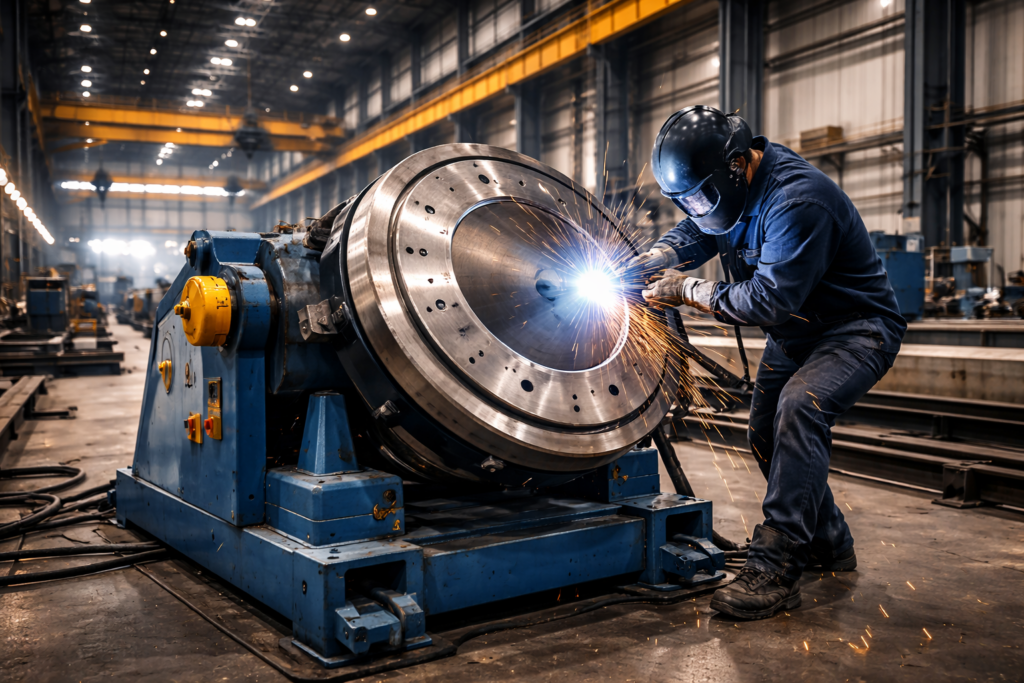
Welding thick-walled pressure vessels in overhead or vertical configurations leads to heat control issues, slag inclusion, and burn-through. A welding positioner rotates and tilts heavy workpieces so operators perform flat or horizontal down-hand welds.
Down-Hand Welding Advantages:
- Higher Deposition Rates: Increases overall output by 30% to 50%.
- Superior Weld Quality: Achieves deeper penetration depth and uniform bead profiles.
- Minimal Defects: Significantly reduces heat distortion and slag inclusions.
- Ergonomic Safety: Lowers operator fatigue and reduces workplace risk.
Down-hand positioning allows higher current settings, larger electrode wire diameters, and faster travel speeds. This shift boosts metal fabrication efficiency while preserving high-quality weld profiles.
Positioners vs. Turntables vs. Rotators
Heavy fabrication shops rely on three primary workpiece manipulation technologies:
- Welding Positioner: Multi-axis equipment equipped with a tilting and rotating faceplate table. Ideal for dish ends, complex structural nozzles, flanges, and asymmetric vessel components.
- Welding Turntable: A single-axis motorized platform designed exclusively for horizontal rotation. A welding turntable excels at circumferential joint welding when paired with fixed column and boom setups.
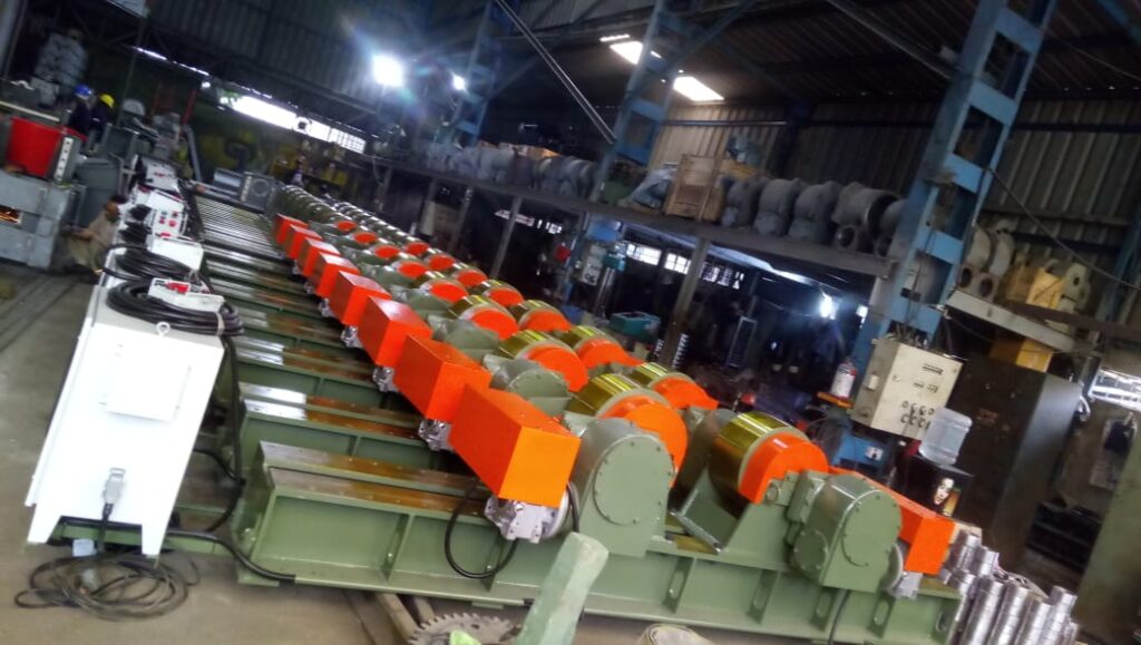
- Welding Rotators: Roller-bed setups (such as conventional or self-aligning turning rolls) built to support and turn long, cylindrical vessel shells during longitudinal and girth-seam welding.
5 Critical Factors for Selecting Heavy Vessel Welding Positioners
Selecting heavy vessel equipment requires balancing mechanical physics with daily production demands. Evaluate these five core parameters before investing in new machinery.
1. Accurate Load Capacity Assessment
Equipment capacity rating is the foundation of shop safety and equipment longevity. Overloading leads to mechanical strain, drive gear failure, and unsafe operation.
- Gross Vessel Weight: Calculate the total weight of the bare vessel shell, internal baffles, flanges, nozzles, and attached weld fixturing.
- Dynamic Loading: Account for torque spikes generated when high-inertia vessels start or stop rotating.
- Safety Margins: Always size your welding positioner machine with a minimum 20% to 25% safety buffer above your heaviest anticipated payload.
For assistance matching equipment capacity to complex production workflows, consult the engineering specialists at Cu-Built Engineers.
2. Center of Gravity (CG) and Center of Torque Calculation
Center of Gravity (CG) dictates how weight distributes across the tilt axis and rotation axis. As a vessel section tilts away from vertical center, gravity exerts extreme rotational force against the motor drives.
- Center of Gravity (CG) Distance: Measure the distance from the table surface to the center mass of the workpiece. Higher CG values reduce net payload capacity.
- Center of Offset (Eccentricity): Measure the distance from the rotation center to the mass center. Off-center nozzle loads demand high-torque drives to maintain smooth, continuous motion.
Calculate both CG and torque offset together. Placing a 10-ton asymmetric shell on a 10-ton standard positioner often causes drive failure if the payload CG extends past the machine rating envelope.
3. Axis Configuration: Gear-Driven vs. Hydraulic Positioning
Choosing between gear-driven mechanical positioning and hydraulic motion systems depends on workpiece geometry and total payload weight.
Gear-Driven Systems:
- Uses precision motor reducers, self-locking worm gears, and heavy slewing rings.
- Delivers zero-backlash rotation for consistent continuous arc welding.
- Excellent for light to medium-heavy vessels up to 20 Metric Tons.
Hydraulic Rotation Systems:
- Employs high-pressure hydraulic cylinders to handle extreme tilt moments.
- A hydraulic rotation welding positioner provides smooth height adjustment and tilt action for giant industrial vessels weighing 50 to 150+ Tons.
- Built-in hydraulic safety valves prevent sudden table drop during power interruptions.
4. Drive Motors and Rotation Control
Inconsistent table rotation causes weld bead defects, uneven penetration, and unexpected arc outages.
- Variable Frequency Drives (VFD): Provide precise AC motor control to maintain consistent surface speeds across varying vessel diameters.
- Zero-Backlash Gearboxes: Eliminate backlash pauses when rotating off-balanced vessel components.
- Precision Speed Regulation: Ensure travel speed stays within tight ranges (e.g., 0.05 to 1.5 RPM) for automatic Submerged Arc Welding (SAW) and Gas Metal Arc Welding (GMAW).
5. Table Faceplate Options and Clamping Integration
Your positioner table surface must secure heavy vessel components without distortion or dynamic slip.
- Concentric Machined Rings: Provide fast visual centering for round dish ends and cylindrical shells.
- Radial T-Slots: Accept heavy-duty mechanical tie-downs, hydraulic clamps, or custom modular tooling.
- Specialized Jigs: An automated welding turntable with modular fixturing accelerates piece-to-piece changeovers in repeatable vessel assembly lines.
Explore specialized workholding tools and custom automation designs by visiting Cu-Built Welding Automation Systems.
Specialty Positioners for Complex Vessel Architectures
Heavy vessels feature unique geometries that often demand dedicated positioning machinery rather than standard single-table equipment.
Tilt-Rotate Positioners
A tilt-rotate positioner provides 135-degree forward/backward table tilt combined with continuous 360-degree rotation. This dual-axis capability lets welders position complex vessel head nozzles, manway branches, and internal support rings into horizontal welding orientation without using overhead cranes.
Pipe Welding Positioners for Nozzle Stubs and Spools
Integrating pipe branches, flanges, and high-pressure steam stubs onto vessel shells requires precise rotational control. A high-torque pipe welding positioner handles small-to-medium nozzle assemblies, giving operators full 360-degree access for smooth root-pass TIG and automated MIG fill passes.
Headstock and Tailstock Systems for Extra-Long Vessels
When pressure vessels exceed standard length limits, a single-table positioner becomes unstable due to high overhang torque. Headstock and tailstock setups split the load:
- Headstock Unit: Powered motor drive unit mounted to a fixed floor base.
- Tailstock Unit: Idler unit mounted on linear floor rails, providing adjustable bed spacing to support varied vessel lengths.
- Combined Operation: Elevating headstock-tailstock systems lift and manipulate long cylindrical vessels simultaneously, removing dangerous mid-span sagging forces.
Learn how heavy structural handling configurations streamline vessel production by reviewing Cu-Built Material Handling Solutions.
Integrating Positioners with Welding Automation Systems
Combining heavy-duty positioning machinery with modern automated welding columns yields unmatched seam quality and production speed.
Submerged Arc Welding (SAW) and Column & Boom Setup
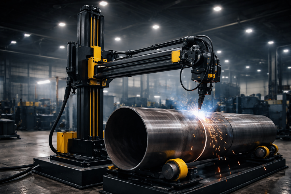
High-output pressure vessel fabrication relies on automated Submerged Arc Welding (SAW). Installing an automated welding turntable alongside a heavy-duty welding column and boom creates an integrated automated cell.
- Synchronized Motion: The PLC controller locks the column boom travel speed to match the positioner’s surface rotation rate, keeping the weld pool stable.
- Continuous Wire Feed: Large payload positioning keeps the circumferential seam perfectly horizontal, allowing continuous deep-penetration multi-pass deposition.
Safety and Operational Controls
Automating heavy workpiece positioning improves operator safety while increasing arc-on time.
- Pendant Controllers: Lightweight handheld pendants let welders adjust rotation speed and tilt angles from safe working distances.
- Foot Pedal Integration: Keeps operator hands free to adjust torch angle, wire feed position, and seam tracking controls.
- Encoder Integration: Absolute rotary encoders send real-time speed data back to centralized robotic controllers for exact weld seam repeatability.
Understanding industrial automation standard practices is critical for heavy equipment deployments. Review detailed technical guidelines on standard equipment safety practices from OSHA Safety and Health Standards and structural welding specifications from the American Welding Society (AWS).
Operational Safety and Preventative Maintenance Protocols
Positioning industrial vessels weighing tens of tons introduces operational hazards that require strict safety protocols and regular maintenance schedules.
Workpiece Clamping Verification
Never rely on friction alone when securing a heavy dish end or vessel cylinder to a table faceplate.
- Use hardened steel stop blocks welded directly to modular table plates.
- Torque high-tensile clamping bolts using calibrated torque wrenches before tilting.
- Run a full 360-degree dry-rotation test cycle at maximum tilt angle to check clearance and balance before starting the arc.
Anti-Backlash Gear Protection
Eccentric vessel loads cause backlash chatter, which accelerates gear tooth wear and leads to irregular surface rotation speeds.
- Inspect table pinion gears, worm drives, and main slewing bearings monthly.
- Use specialized synthetic gear lubricants built to withstand extreme pressure and vibration.
- Check hydraulic fluid cleanliness, pressure relief settings, and cylinder seals on every hydraulic rotation welding positioner setup.
Selecting the Right Welding Positioner: Step-by-Step Checklist
- Calculate Maximum Payload Weight: Include bare metal shell weight, end heads, internal accessories, and clamping fixtures.
- Determine CG and Offset Center: Calculate distance from table faceplate to load center to prevent drive overload.
- Select Ideal Axis Motion: Match geometry requirements against dual-axis positioners, headstock systems, or turning rolls.
- Choose Drive & Power Requirements: Specify variable-speed VFD electric motors or high-capacity hydraulic lift systems based on dynamic weight requirements.
- Confirm Workholding Setup: Select concentric rings, t-slot tables, or custom jigs built for your primary vessel line.
- Verify Shop Floor Footprint: Ensure foundation slab thickness, overhead crane clearances, and power utilities match equipment specifications.
Boost Fabrication Output with Cu-Built Engineering Solutions
Selecting the ideal positioning machinery requires balancing load dynamics, mechanical drive design, and modern welding automation integration. Installing high-performance welding rotators, specialized turntables, or multi-axis positioners protects your shop against structural weld defects, unsafe handling practices, and costly production delays.
Ready to upgrade your heavy vessel fabrication setup? Cu-Built Engineers designs and builds high-capacity industrial automation equipment tailored to your exact production demands.
Contact our engineering team today at sales@cubuilt.com or call +91 97300 89705 to request a custom consultation, download product specifications, and optimize your welding shop performance.
Frequently Asked Questions (Q&A)
Q1: What is the main difference between a welding positioner and a welding rotator?
A welding positioner uses a powered tilting and rotating table faceplate to manipulate asymmetric components, dish ends, and flanged assemblies across multiple axes. A set of welding rotators (or turning rolls) uses roller wheels to support and rotate long cylindrical vessel shells horizontally during longitudinal and circumferential seam welding.
Q2: How do I calculate Center of Gravity (CG) for an irregular heavy vessel workpiece?
Measure the distance from the positioner table surface to the center of mass of the combined vessel and fixture payload. Multiply this length by the total payload weight to derive the total tilt moment. Always compare your final calculated moment against the manufacturer’s load-capacity curve to prevent drive unit failure.
Q3: Why should I choose a hydraulic rotation welding positioner instead of a gear-driven model?
A hydraulic rotation welding positioner provides higher lifting force, smoother height adjustment, and greater tilt-torque capacity. It is ideal for heavy industrial pressure vessels weighing over 20 to 50 Tons, where mechanical gear drives face severe tooth stress.
Q4: Can a welding positioner integrate with robotic or automatic column-and-boom setups?
Yes. Modern positioners feature VFD drive motors, precision encoders, and digital interface cards that link directly into central PLC systems. This connectivity lets an automated welding turntable synchronize speed with welding booms for continuous automated Submerged Arc Welding (SAW).
Q5: How does a welding positioner machine improve shop safety?
It eliminates the need for operators to perform dangerous overhead or vertical welds and reduces crane repositioning cycles. By presenting every weld seam in the flat down-hand position, it minimizes operator fatigue, burn hazards, and workpiece handling risks.