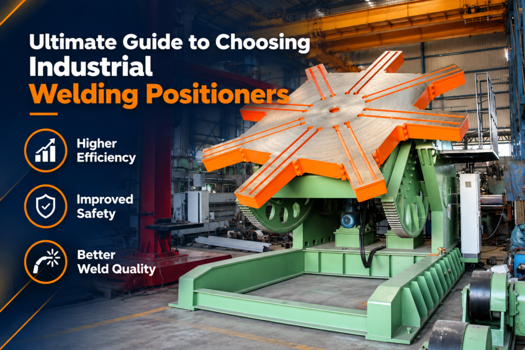
Modern heavy manufacturing and structural fabrication demand structural integrity, precision, and operational efficiency. In sectors such as aerospace, heavy engineering, shipbuilding, power generation, and pressure vessel fabrication, relying on manual workpiece manipulation and overhead crane repositioning is no longer viable. Introducing a high-performance welding positioner machine into your production floor changes how heavy structural elements are handled, rotated, tilted, and joined.
However, choosing the correct machine configuration—whether you need a versatile welding turntable, specialized welding rotator price analysis for capital budgeting, or heavy-duty machinery from certified welding rotator manufacturers in india—demands thorough engineering evaluation.
This comprehensive guide explores technical parameters, structural layouts, kinematic calculations, safety considerations, and economic justifications for selecting optimal automated positioning systems for heavy industrial workloads.
Understanding the Role of a Welding Positioner Machine in Modern Fabrication
Heavy fabrication facilities face persistent challenges regarding massive workpiece weight, asymmetrical geometries, and strict non-destructive testing (NDT) quality standards. When welders attempt to work on stationary parts or rely repeatedly on overhead shop cranes to turn heavy weldments, several operational issues arise:
- Production Bottlenecks: Cranes remain tied up for extended turning maneuvers, keeping other workstations idle.
- Weld Quality Degradation: Out-of-position welding (such as vertical-up or overhead welding) requires higher skill, slows down deposition rates, and significantly increases the risk of inclusions, undercut, and porosity.
- Safety Hazards: Suspending multi-ton structures with rigging chains while operators work beneath or beside them introduces severe safety risks.
A precision-engineered welding positioner machine eliminates these challenges by clamping, tilting, and rotating components into the flat or down-hand (1G/1F) position. By presenting the joint in an optimal down-hand orientation, the welder or automated torch can utilize higher current settings, larger electrode wire diameters, and maximum deposition rates.
When integrated alongside advanced automated welding equipment, industrial positioners allow shop floors to achieve uniform bead profiles, deeper joint penetration, and faster cycle times across every production shift.
Key Types of Positioning Equipment for Heavy Industry
Selecting the right mechanical positioning system starts with understanding the primary equipment categories designed for heavy industrial applications.
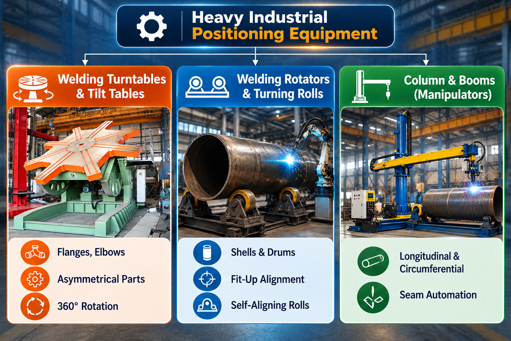
1. Welding Turntables and Tilt-Frame Positioners
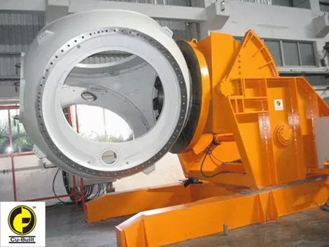
For circular assemblies, flanges, large valves, elbows, and structural frames, a dedicated welding turntable delivers smooth, motorized 360-degree rotation along with controlled forward/reverse tilting (typically from 0° to 120° or 135°).
- Benchtop and Floor-Mounted Models: Small components benefit from compact benchtop units, while multi-ton heavy assemblies utilize low-profile, floor-anchored positioners with reinforced gears.
- Headstock and Tailstock Systems: For extremely long, linear structural beams or chassis frames, dual headstock-tailstock setups operate in unison, supporting both ends to eliminate center sag and torsion stresses.
2. Welding Rotators and Tank Turning Rolls
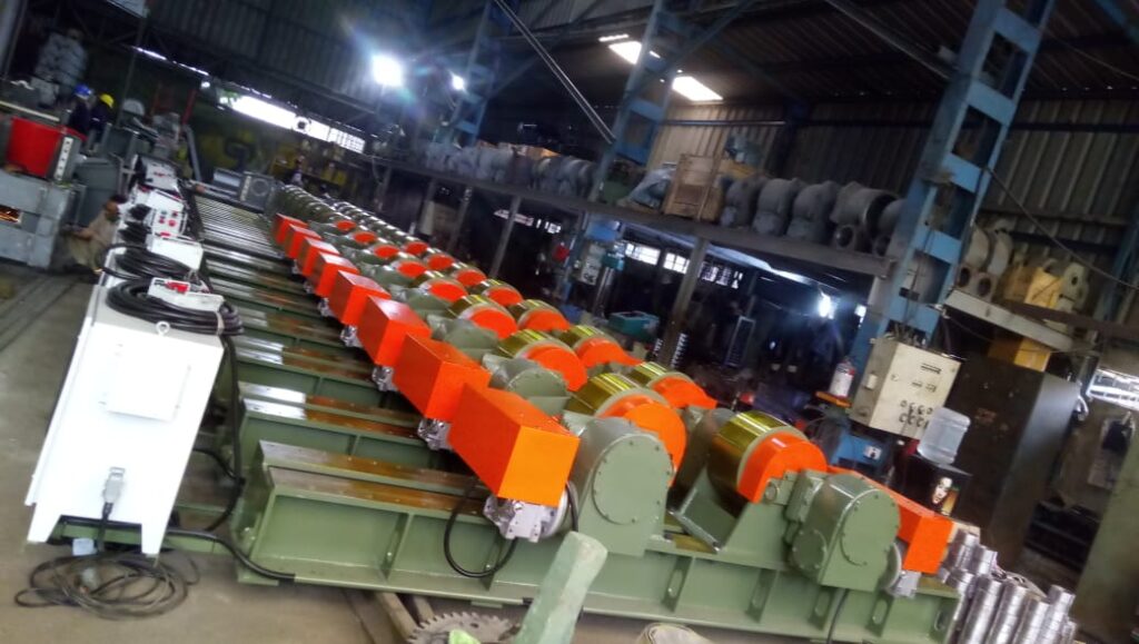
When handling long cylindrical structures like pipes, pressure vessels, boilers, and wind tower segments, rotators are the industry standard.
- Conventional Rotators: Feature manual pin or lead-screw adjustments to alter wheel center distances to match varying pipe diameters.
- Self-Aligning Rotators: Utilize articulated rocker arm assemblies that automatically adjust roller positions to accommodate varying shell diameters without manual mechanical adjustments.
- Fit-Up Rotators: Equipped with hydraulic or motorized alignment rollers that allow fine-tuning of axial and radial alignment, streamlining tack-welding phases during vessel fabrication.
3. Integrated Column and Boom Systems
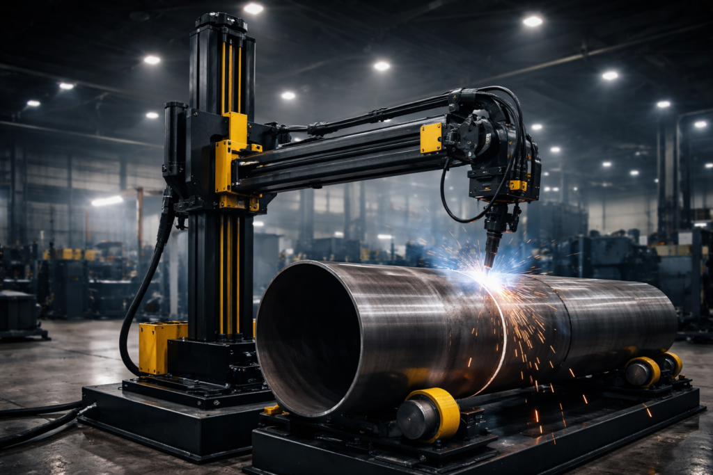
To maximize output, positioning units are paired with heavy-duty column and boom systems (also known as welding manipulators). The manipulator holds and feeds the welding head while the underlying positioner or rotator rotates the component beneath it. This setup enables continuous, defect-free circumferential seam welding on critical containment vessels and high-pressure piping.
Core Technical Criteria for Selecting Industrial Positioners
Selecting the right machinery requires matching operational demands with engineering specifications. Oversights in calculations can lead to mechanical overload, unstable rotation, or equipment failure.
1. Load Capacity, Center of Gravity (CG), and Overturning Moment
The most vital specification is total weight capacity. However, weight alone is insufficient. Engineers must evaluate:
- Center of Gravity Distance (CG): The distance from the faceplate table surface to the center of mass of the component.
- Eccentricity (E): The offset distance from the center of rotation to the component’s center of mass.
An asymmetrical workpiece creates a rotational torque and an overturning moment. If the CG is offset too far from the tilt axis, the tilting motor may stall or burn out, even if the total load is below the maximum weight threshold.
2. Rotation, Tilt Speed, and Drive Mechanisms
Varying processes—such as Submerged Arc Welding (SAW), Gas Metal Arc Welding (GMAW/MIG), or Gas Tungsten Arc Welding (GTAW/TIG)—demand precise rotational speeds.
- Look for systems equipped with Variable Frequency Drives (VFD) or AC servo motors that provide stepless speed control, maintaining smooth rotation at ultra-low speeds without cogging or vibration.
- Backlash-free gearboxes are critical when working with robotic arms or automatic tracking sensors.
3. Electrical Grounding and Current Collections
Heavy industrial submerged arc or flux-cored arc welding involves welding currents ranging from 400A to over 1200A. If the positioner lacks a built-in current collector, the current will pass through internal bearings and gearboxes. This causes electrical arcing, pitting, gear erosion, and premature bearing destruction. Look for heavy-duty, spring-loaded copper-graphite grounding brushes that handle continuous high-amperage transfer directly to the base frame.
Application Spotlight: Vessel Fabrication and Heavy Infrastructure
Heavy industries rely on high-capacity positioning systems to maintain tight manufacturing tolerances across challenging environments:
| Industry Sector | Primary Workpiece Profiles | Preferred Positioning Setup | Key Operational Advantage |
| Pressure Vessel Fabrication | Boiler drums, storage tanks, heat exchangers | Self-aligning rotators + Column and boom manipulators | Automated circumferential seam welding with consistent penetration |
| Shipbuilding & Marine | Structural hull sections, rudder stocks, marine pipes | High-tonnage hydraulic tilt turntables | Eliminates overhead crane dependencies and improves welder safety |
| Wind Energy Equipment | Monopile foundations, tower shell segments | Fit-up rotators with hydraulic level adjustment | Accelerates shell-to-shell alignment and tack-welding operations |
| Heavy Machinery & Defense | Excavator booms, crane arms, armored vehicle hulls | Headstock-tailstock positioners with dual-axis sync | Enables full 360° down-hand access for multi-pass thick plate welds |
Applying these integrated configurations ensures that critical weld joints meet demanding radiographic and ultrasonic inspection standards on the first pass.
Evaluating Cost Factors and Sourcing from Reliable Manufacturers
When evaluating capital expenditures, engineering and procurement teams look closely at overall welding rotator price structures alongside total cost of ownership (TCO).
Capital Investment vs. Long-Term Productivity Gains
While lower-cost alternatives may seem financially attractive initially, they often lack structural stiffness, precise gear machining, and dynamic safety braking systems. Equipment failures in heavy plants cause costly downtime that quickly outweighs upfront equipment savings. Investing in robustly built machinery ensures:
- Higher duty cycles under continuous multi-shift production.
- Lower maintenance costs over decades of operation.
- Enhanced safety interlocks, thermal overload protection, and emergency stop circuits.
Benefits of Sourcing from Established Manufacturers
Partnering with verified welding rotator manufacturers in india—known for heavy structural fabrications and precision machinery—delivers several clear advantages:
- Custom table dimensions, mounting slots, and height variations tailored to your workshop dimensions.
- Ready availability of replacement gears, motors, drive wheels, and electrical panels.
- Expert local engineering support for commissioning, calibration, and operator training.
To review a wide selection of robust positioning, turning, and material handling systems designed for heavy industrial environments, explore specialized solutions at Cubuilt. For additional technical standard specifications and safety guidelines for mechanical handling, consult reference documentation from the American Welding Society. You can also research broader industrial automation insights and machinery trends on Industrial Plant and Equipment.
Best Practices for Operational Maintenance and Safety
Installing heavy positioning machinery requires adhering to maintenance and safety routines to ensure long-term performance and worker protection:
- Daily Visual Checks and Lubrication: Ensure drive gears, worm screws, and pinion paths are lubricated with high-pressure grease. Clean slag accumulation away from table rotation tracks.
- Grounding Brush Inspections: Inspect copper-graphite grounding brushes weekly to ensure adequate contact pressure and replace worn brushes before arcing damages internal shaft bearings.
- Polyurethane Wheel Maintenance: For rotators equipped with polyurethane tires, check for surface wear or embedded metal chips. Clean tires regularly to prevent slippage during vessel rotation.
- Anchor Integrity Checks: Verify that floor anchoring bolts and frame leveling pads remain torqued, especially when high-tilting moments are regularly applied.
Streamlining Heavy Fabrication: Pitch for Professional Services
Integrating automated positioning machinery requires layout planning, accurate load calculations, and tailored integration with your current welding power sources. Selecting mismatched components or incorrectly calculating center-of-gravity offsets can lead to operational friction, weld defects, and safety risks.
At Cubuilt, our engineering team specializes in custom designing and manufacturing industrial turnkey fabrication equipment built for high production demands. Whether your facility needs custom-engineered high-tonnage positioners, self-aligning turning rolls, pipe fit-up stations, or complete robotic welding cells, our specialists deliver end-to-end guidance—from design and manufacturing to site commissioning.
Ready to elevate your facility’s fabrication efficiency and safety? Connect with our engineering specialists today at Cubuilt Contact to request a custom consultation, load calculation review, or detailed product brochure.
Frequently Asked Questions (Q&A)
Q1: How do I calculate the required weight capacity and CG offset for a positioner?
Calculate the total weight of the workpiece including all stiffeners, fixtures, and attachments. Next, determine the distance from the table surface to the center of gravity (CG) as well as any off-center rotation distance (eccentricity). Cross-reference these values against the manufacturer’s load-torque rating curves. It is best practice to include a 20% to 30% safety margin above your maximum static load.
Q2: Can a welding positioner machine be integrated with robotic systems?
Yes. Modern positioners equipped with absolute encoders, backlash-compensated gearboxes, and servomotors can be fully synchronized with 6-axis industrial robots or automatic seam trackers. This allows the robot and the positioner to move in complete unison during continuous deposition paths.
Q3: What is the main operational difference between conventional and self-aligning rotators?
Conventional rotators require operators to manually move wheel brackets along bolt slots or lead screws to fit different vessel diameters. Self-aligning rotators feature pivoted four-wheel rocker assemblies that automatically adjust their angle to fit varying vessel diameters without manual setup adjustments.
Q4: Why is dedicated electrical grounding essential on positioners?
A dedicated high-capacity grounding system ensures that high welding currents flow safely from the workpiece back to the power source. Without a dedicated grounding path, electric current travels through gear teeth and bearing assemblies, causing micro-arcing that pits precision components and leads to premature mechanical failure.
Q5: How do fit-up rotators speed up vessel fabrication?
Fit-up rotators feature independent hydraulic or motorized adjustment of individual roller wheels in upward, downward, or side-to-side directions. This allows operators to align the edges of two separate shell rings precisely for tack welding, cutting alignment setup times significantly compared to using overhead cranes.